80. High-Frequency Pulses Counter
Problem Understanding
We need to:
- Count incoming pulses up to a maximum of 8 MHz frequency.
- Display the pulse count on a serial terminal (e.g., PuTTY) only when a push button is pressed.
- Reset the count to 0 after displaying.
- Pulse generation can be from any source (function generator, another MCU, etc.).
Key Technical Challenges
- High-frequency handling (8 MHz is far beyond CPU polling capability).
- Count accuracy without missing pulses.
- Debouncing the push button press detection without affecting pulse counting.
- Synchronizing high-speed counter reads with low-speed UART printing.
Recommended Approach
We use:
- Any MCU with a high-speed hardware timer configured in External Clock Mode, directly clocked by the pulse signal — this ensures counting at hardware speed without CPU intervention.
- GPIO for push button press detection.
- UART for sending the count to the serial terminal.
Why External Clock Mode?
Because it allows the timer’s counter to increment on each incoming pulse directly from the pin’s input capture hardware, bypassing CPU limitations.
System Architecture
| Component | Function |
| TIMx (32-bit or overflow logic) | Counts pulses at hardware speed up to 8 MHz |
| Push Button | Trigger data read and reset count |
| UART | Sends pulse count to serial terminal |
| EXTI | Detects push button press |
| Software ISR | Reads count, sends via UART, clears counter |
Implementation Steps
Step 1 — Configure Timer in External Clock Mode
- Select any high-speed capable timer.
- Set Clock Source = External Trigger.
- Edge detection = Rising edge (or falling, depending on signal).
- No prescaler (PSC = 0).
- Maximum Count Value = 0xFFFFFFFF (max for 32-bit count).
Effect: Each incoming pulse increments TIM->CNT in hardware at up to 8 MHz.
Step 2 — Configure Push Button Input
- Set the button pin as a GPIO Input with a pull-up.
- Add software debounce (~50 ms delay or state check).
Step 3 — Configure UART
- Baud rate: e.g., 115200.
- Send data in printf style for readability on a serial terminal.
Step 4 — Main Code Flow
- Start the hardware timer counter.
- Poll for button press detection.
Advantages of This Approach
- No CPU overhead for counting — hardware timer handles 8 MHz easily.
- High accuracy — no missed pulses.
- Scalable — can handle even higher frequencies depending on timer input specs.
So, by considering the above points, we can implement the task.
Below are the solutions to the given task using different microcontrollers
- STM32
- ESP32
- Arduino UNO
We’re using an STM32 NUCLEO-F103RB board.
Key Peripherals Used:
- Timer2 (TIM2): Used for pulse counting
- USART2: For serial communication to display results
- GPIOA Pin 8: User button input
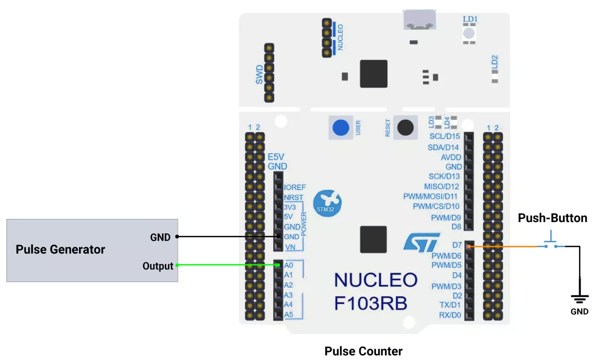
STM32 Hardware Connections
Step-by-Step Pin Mapping:
- Push Button:
- One terminal to PA8.
- Other terminal to GND.
- Configure PA8 with an internal pull-up.
- Pulse Input Source:
- Output pin (e.g., another MCU, signal generator) to PA0 (TIM2 ETR).
- Ensure voltage levels match STM32 I/O specs.
- UART Serial Output:
- PA2 (USART2 TX) to USB/Serial adapter or onboard ST-Link virtual COM port.
- PA3 (USART2 RX) is not required for one-way display.
Circuit Diagram
STM32 Firmware Implementation
Project Setup in STM32CubeIDE
- Create a Project
- Open STM32CubeIDE and start a new project, select the NUCLEO-F103RB board.
- Basic Configuration (via CubeMX inside CubeIDE)
- Clock: Keep the default internal oscillator (no custom changes needed).
- GPIO:
- Push-Button: Set PA8(D7) as GPIO Input with Pull-Up
- Configure TIM2
- Enable TIM2
- Slave Mode: External Clock Mode 1
- Trigger Source: ETR1
- Interrupt: Enable TIM2 Global Interrupt in NVIC.
- Enable TIM2
- UART2
- Set Mode to Asynchronous
- Baud Rate: 115200
- Word Length: 8 bits
- Parity: None
- Stop Bits: 1
- Hardware Flow Control: None
- The NUCLEO-F103RB board has USART2 connected to the ST-LINK virtual COM port (PA2 and PA3)
- Code Generation
- CubeMX will automatically generate all the startup code, including:
HAL_Init()– Initializes the HAL library.SystemClock_Config()– Configures the system clock.MX_USART2_UART_Init()→ Sets up USART2.MX_GPIO_Init()– Configures GPIOs.MX_TIM2_Init()– Configures TIM2.
- This code sets up the hardware and prepares the project for firmware development, so we only need to add our application logic in the user code sections
- CubeMX will automatically generate all the startup code, including:
Code Snippets from main.c
Timer 2 initialization
void MX_TIM2_Init(void) {
  htim2.Instance = TIM2;
  htim2.Init.Prescaler = 0;
  htim2.Init.CounterMode = TIM_COUNTERMODE_UP;
  htim2.Init.Period = 65535;
  htim2.Init.ClockDivision = TIM_CLOCKDIVISION_DIV1;
  htim2.Init.AutoReloadPreload = TIM_AUTORELOAD_PRELOAD_DISABLE;
  HAL_TIM_Base_Init(&htim2);

  TIM_SlaveConfigTypeDef sSlaveConfig;
  sSlaveConfig.SlaveMode = TIM_SLAVEMODE_EXTERNAL1;
  sSlaveConfig.InputTrigger = TIM_TS_ETRF;
  HAL_TIM_SlaveConfigSynchro(&htim2, &sSlaveConfig);
}- Configures Timer2 for 16-bit external clock pulse counting.
- Enables external trigger on PA0 (ETR).
UART Setup
void MX_USART2_UART_Init(void) {
  huart2.Instance = USART2;
  huart2.Init.BaudRate = 115200;
  huart2.Init.Mode = UART_MODE_TX_RX;
  HAL_UART_Init(&huart2);
}- Baud rate: 115200, 8-bit data, no parity, 1 stop bit.
GPIO Setup (Button with Pull-Up)
void MX_GPIO_Init(void) {
  GPIO_InitTypeDef GPIO_InitStruct = {0};
  GPIO_InitStruct.Pin = GPIO_PIN_8;
  GPIO_InitStruct.Mode = GPIO_MODE_INPUT;
  GPIO_InitStruct.Pull = GPIO_PULLUP;
  HAL_GPIO_Init(GPIOA, &GPIO_InitStruct);
}- Initializes PA8 as a digital input with an internal pull-up resistor enabled.
User Code and Main Loop Logic
// Track timer overflow for 32-bit pulse count
volatile uint32_t g_overflowCounter = 0;

// TIM2 overflow callback handler
void HAL_TIM_PeriodElapsedCallback(TIM_HandleTypeDef *htim) {
    if (htim->Instance == TIM2) {
        g_overflowCounter++; // Extend counter beyond 65535
    }
}

int main(void) {
    HAL_Init();
    SystemClock_Config();

    MX_GPIO_Init();
    MX_USART2_UART_Init();
    MX_TIM2_Init();

    // Start TIM2 base in interrupt mode
    HAL_TIM_Base_Start_IT(&htim2);
    g_overflowCounter = 0;

    while (1) {
        // Check if button (PA8) is pressed (active low)
        if (HAL_GPIO_ReadPin(SWITCH_PORT, SWITCH_PIN) == GPIO_PIN_RESET) {
            uint32_t count = __HAL_TIM_GET_COUNTER(&htim2) + (65536 * g_overflowCounter);

            char buff;
            sprintf(buff, "Count = %lu \r\n", (unsigned long int)count);
            HAL_UART_Transmit(&huart2, (uint8_t *)buff, strlen(buff), 100);

   //Resets the counter
g_overflowCounter = 0;

// Set TIM2 counter to 0
__HAL_TIM_SET_COUNTER(&htim2, 0);

            // Button debounce, delay
            HAL_Delay(1000);
        }
    }
}
Explanation:
- Overflow Extension:
g_overflowCounteris used to extend the 16-bit TIM2 counter (max 65,535) into a virtual 32-bit counter by incrementing on every timer overflow. - Interrupt Handling: HAL_TIM_PeriodElapsedCallback() is triggered when TIM2 overflows, incrementing g_overflowCounter.
- Initialization: HAL, system clock, GPIO, UART, and TIM2 are initialized. TIM2 is started in interrupt mode to enable overflow tracking.
- Main Loop:
- When the user presses the button (PA8, active-low), the code reads the current TIM2 count and adds
65536 × g_overflowCounter→ giving the total pulse count since start. - The count is formatted into a string and sent over UART2.
- Reset: After sending, both the overflow counter and TIM2 counter are reset to zero, so counting restarts fresh.
- A HAL_Delay(1000) provides simple debounce and prevents multiple rapid prints.
- When the user presses the button (PA8, active-low), the code reads the current TIM2 count and adds
Key STM32/HAL-Specific Notes
- External Clock Mode: For accurate, high-frequency pulse counting, always use the timer external clock mode, not interrupts.
- Overflow Handling: Ensure ISR is enabled for timer overflow (HAL_TIM_Base_Start_IT).
- Pin Mapping: ETR input pin varies; PA0 for TIM2 is standard on Nucleo-F103RB. Check the reference manual for other STM32s.
- UART Console: Ensure terminal settings match baud rate (115200, 8N1).
Expected Output
When the push button (PA8) is pressed:
- STM32 outputs the total pulses counted to the UART terminal.
- Output format: Count = XXXXX
- Counter resets for next measurement.
Typical UART Console Output:
Count = 83625Download Project
The complete STM32CubeIDE project (including .ioc configuration, main.c, and HAL files) is available here:
📥 Download Project
- We are using the ESP32 DevKit v4 development board and programming it using the Arduino IDE.
- Before uploading, make sure to select “ESP32 Dev Module” as the board to ensure correct settings and compatibility.
- The ESP32 has four general-purpose hardware timers, primarily designed for time-keeping and interrupt-driven tasks (e.g., delays, periodic events, scheduling), and cannot count external pulses.
- For an external pulse counting application, there is dedicated hardware in the ESP32 called PCNT.
- So in the given task, we will use the PCNT hardware module to perform the given task.
Note: Although the task mentions using a timer, ESP32’s general-purpose timers don't have the ability to count external pulses. So use the PCNT (Pulse Counter) peripheral, which is dedicated hardware for reliable external pulse counting.
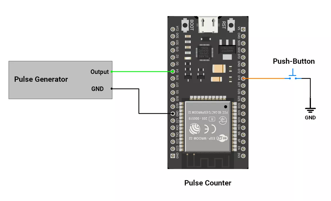
ESP32 Circuit Connection
- Connect external pulses to GPIO pin 4.
- Interface push button switch to GPIO pin 14 with internal pullup configuration.
ESP32 Code
#include <Arduino.h>
#include "driver/pcnt.h"

#define SWITCH_PIN 14        // Button input (active LOW with INPUT_PULLUP)
#define PULSE_PIN  4         // Pulse input pin (3.3V logic)
#define DEBOUNCE_DELAY 50    // Button debounce time (ms)

// Button debounce state
bool last_button_state = HIGH;
bool current_button_state = HIGH;
unsigned long last_debounce_time = 0;

// PCNT (Pulse Counter) setup
#define PCNT_UNIT    PCNT_UNIT_0         // Use PCNT unit 0
#define PCNT_CHANNEL PCNT_CHANNEL_0      // Use channel 0 of the unit
volatile int32_t overflowCount = 0;      // Software overflow counter (extended width)

// PCNT interrupt handler: called when the hardware counter hits the high limit.
void IRAM_ATTR pcnt_intr_handler(void *arg) {
  uint32_t status = 0;
  pcnt_get_event_status(PCNT_UNIT, &status);     // Read and clear event status bits

  if (status & PCNT_EVT_H_LIM) {                 // High-limit reached (0..32767)
    overflowCount++;                              // Extend count by tracking overflows
  pcnt_counter_clear(PCNT_UNIT);  // reset HW count to 0 so next block can accumulate

  }
  // Underflow not used in this project
}

// Configure and start PCNT to count rising edges on PULSE_PIN.
void pcnt_init() {
  pcnt_config_t pcnt_config = {};
  pcnt_config.pulse_gpio_num  = PULSE_PIN;        // Count pulses arriving on this GPIO
  pcnt_config.ctrl_gpio_num   = PCNT_PIN_NOT_USED;// No control pin
  pcnt_config.unit            = PCNT_UNIT;
  pcnt_config.channel         = PCNT_CHANNEL;
  pcnt_config.counter_h_lim   = 32767;            // High limit → overflow event
  pcnt_config.counter_l_lim   = 0;                // Low limit (not used)
  pcnt_config.pos_mode        = PCNT_COUNT_INC;   // +1 on rising edges
  pcnt_config.neg_mode        = PCNT_COUNT_DIS;   // Ignore falling edges
  pcnt_config.lctrl_mode      = PCNT_MODE_KEEP;   // No control action
  pcnt_config.hctrl_mode      = PCNT_MODE_KEEP;

  pcnt_unit_config(&pcnt_config);                 // Apply configuration

  pcnt_event_enable(PCNT_UNIT, PCNT_EVT_H_LIM);   // Enable high-limit event interrupt

  pcnt_isr_service_install(0);                    // Install common ISR service (default flags)
  pcnt_isr_handler_add(PCNT_UNIT, pcnt_intr_handler, NULL); // Attach our handler

  pcnt_counter_pause(PCNT_UNIT);                  // Ensure stopped before clearing
  pcnt_counter_clear(PCNT_UNIT);                  // Reset hardware counter to 0
  pcnt_counter_resume(PCNT_UNIT);                 // Start counting
}

void setup() {
  Serial.begin(115200);
  pinMode(SWITCH_PIN, INPUT_PULLUP);              // Button uses internal pull-up
  pcnt_init();                                    // Start PCNT counting
}

void loop() {
  // On a debounced button press: read, print, and reset counts
  if (is_debounced_press(SWITCH_PIN)) {
    int16_t count = 0;
    pcnt_get_counter_value(PCNT_UNIT, &count);    // Read current 0..32767 hardware count

    // Each overflow represents 32768 counts (0..32767 inclusive)
    uint32_t totalPulses = (overflowCount * 32768u) + (uint16_t)count;

    Serial.print("Number of Pulses: ");
    Serial.println(totalPulses);

    pcnt_counter_clear(PCNT_UNIT);                // Clear hardware counter for next window
    overflowCount = 0;                            // Clear software overflow extension
  }
}

// Debounce helper: returns true exactly once per valid button press.
bool is_debounced_press(int button_pin) {
  int reading = digitalRead(button_pin);

  if (reading != last_button_state) {             // Edge detected → restart debounce timer
    last_debounce_time = millis();
  }
  last_button_state = reading;

  if ((millis() - last_debounce_time) > DEBOUNCE_DELAY) {
    if (reading != current_button_state) {        // Stable new state
      current_button_state = reading;
      if (current_button_state == LOW) {          // Active-LOW press
        return true;
      }
    }
  }
  return false;
}
Code Explanation
Let’s understand the important parts
pcnt_config_t pcnt_config + pcnt_unit_config(&pcnt_config)- Purpose: Configure the
PCNTperipheral (which GPIO, how to count, and limits). - Here:
pulse_gpio_num = PULSE_PIN→ count edges arriving on this pin.counter_h_lim = 32767, counter_l_lim = 0 → 16-bit-ish window; when 32767 is reached, fire the H_LIM event.pos_mode = PCNT_COUNT_INC→ increment on rising edges.neg_mode = PCNT_COUNT_DIS→ ignore falling edges.ctrl_gpio_num = PCNT_PIN_NOT_USEDand both hctrl_mode/lctrl_mode = KEEP → no control pin, mode stays unchanged.
- In code:
- Purpose: Configure the
pcnt_config_t pcnt_config = {};pcnt_unit_config(&pcnt_config);
pcnt_event_enable(PCNT_UNIT, PCNT_EVT_H_LIM)- Purpose: Turn on the high-limit event, so the unit raises an interrupt when it rolls past 32767.
- Here: Used to extend the counter width in software.
- In code:
pcnt_event_enable(PCNT_UNIT, PCNT_EVT_H_LIM);
pcnt_isr_service_install(0)andpcnt_isr_handler_add(PCNT_UNIT, pcnt_intr_handler, NULL)- Purpose: Install the ISR service and attach your interrupt handler to this PCNT unit.
- Here: Connects your pcnt_intr_handler so it runs on high-limit events.
- In code:
pcnt_isr_service_install(0);pcnt_isr_handler_add(PCNT_UNIT, pcnt_intr_handler, NULL);
void IRAM_ATTR pcnt_intr_handler(void *arg)- Purpose: The ISR that runs when PCNT hits the high limit.
- Here: Reads event status with
pcnt_get_event_status(...).If PCNT_EVT_H_LIM is set, increments overflowCount. In code:
void IRAM_ATTR pcnt_intr_handler(void *arg) {
  uint32_t status = 0;
  pcnt_get_event_status(PCNT_UNIT, &status);
if (status & PCNT_EVT_H_LIM) {
overflowCount++;
}
}
- Why
IRAM_ATTR? Ensures the ISR is placed in internal RAM for reliability/latency. - pcnt_counter_pause/clear/resume
- Purpose: Basic lifecycle control of the hardware counter.
- Here: Start from a clean slate, then begin counting.
- In code:
pcnt_counter_pause(PCNT_UNIT);pcnt_counter_clear(PCNT_UNIT);pcnt_counter_resume(PCNT_UNIT);
pcnt_get_counter_value(PCNT_UNIT, &count)- Purpose: Read the current hardware counter (0…32767).
- Here: Combined with the software overflow to produce a wide total pulses.
- In code:
int16_t count = 0;
pcnt_get_counter_value(PCNT_UNIT, &count);
is_debounced_press(...)- Purpose: Remove switch noise by only accepting a button press after it stays stable for a set time.
- Debounce time is of 50ms.
We are using the Arduino UNO development board and programming it using the Arduino IDE.
- Before uploading, make sure to select “Arduino UNO” as the board to ensure correct settings and compatibility.
We are using a timer to count pulses with External Clock Mode.
- Timers in Arduino UNO:
- Timer0: 8-bit
- Timer1: 16-bit
- Timer2: 8-bit
- Chosen Timer: Timer1 (16-bit)
- It can count up to 65,536 pulses (2^16) before overflowing.
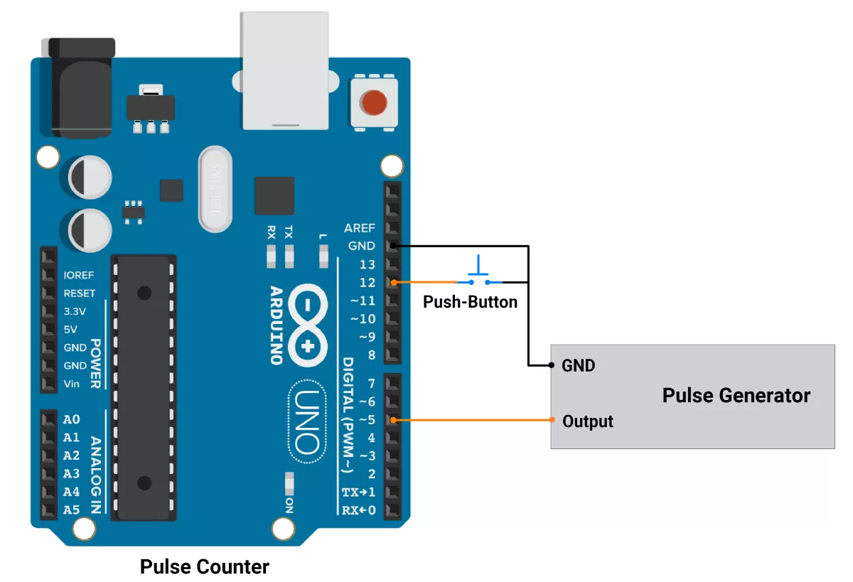
Arduino UNO Hardware Connection
Pulse Counter ( Arduino UNO )
- Connect the board to the PC using a USB cable to establish communication with the Serial Monitor.
- Push Button Switch
- One terminal (NC) is connected to the Digital pin 12 using an internal pull-up.
- The other terminal (NO) is connected to GND.
- Pulse Generator
- Output pin (e.g., another MCU, signal generator) to pin 5 .
- Ensure voltage levels match Arduino UNO’s I/O specs.
The pulse generator produces pulses on the Output Pin, which is connected to digital pin 5 of the pulse counter (Arduino UNO). Digital pin 5 serves as the input for the external clock source to Timer 1.
Arduino UNO Firmware Implementation
- Pulse Counting
- Timer1 is configured as a counter to count external pulses connected to the T1 pin (Arduino pin 5).
- The counter increments on the rising edge of each pulse.
- An overflow interrupt is used to track when the counter exceeds its 16-bit limit (65,536).
Arduino UNO Code
#define SWITCH_PIN 12
#define DEBOUNCE_DELAY 50              // debounce delay

bool last_button_state = 1;            // Previous button state (1: not pressed, 0: pressed)
bool current_button_state = 1;         // Current button state
unsigned long last_debounce_time = 0;  // Timestamp of the last button state change

uint8_t overflowFlag = 0;

void setup() {
  Serial.begin(115200);
  pinMode(SWITCH_PIN, INPUT_PULLUP);
  // Configure Timer1 as a counter
  TCCR1A = 0x00; // Normal mode
  TCCR1B = 0x07; // External clock source on T1 pin, rising edge
  TIMSK1 |= B00000001;  // Enable Timer Overflow Interrupt
  TCNT1 = 0;     // Initialize counter to 0
}

void loop() {

 if (is_debounced_press(SWITCH_PIN)) {
  uint32_t pulseCount = (overflowFlag*65536) + TCNT1;
  Serial.println("Number of Pulses: ");
  Serial.println(pulseCount);
  TCNT1 = 0;
  overflowFlag = 0;
}
}

bool is_debounced_press(int button_pin) {

  int reading = digitalRead(button_pin);


  // If the button state has changed, reset the debounce timer
  if (reading != last_button_state) {
    last_debounce_time = millis();
  }
  last_button_state = reading;
  // If the button state is stable for more than 50 msec the debounce delay, update the state.
  if ((millis() - last_debounce_time) > DEBOUNCE_DELAY) {
    if (reading != current_button_state) {
      current_button_state = reading;
      if (current_button_state == 0) {
        return true;  // valid press detected
      }
    }
  }
  return false;  // No valid press detected
}

ISR(TIMER1_OVF_vect)
{
  overflowFlag++;
}
Code Explanation
- Setup
- Serial communication is initialized.
- Timer1 is configured as a counter.
- The button pin is set as an input with the internal pull-up resistor enabled.
- Loop
- The
is_debounced_press()The function checks for a debounced button press. - If a debounced press is detected:
- The total pulse count is calculated using the formula:
(overflowFlag * 65536) + TCNT1. - The pulse count is printed to the Serial Monitor.
- The Timer1 counter (
TCNT1) and overflow flag (overflowFlag) are reset to 0.
- The total pulse count is calculated using the formula:
- The
- Interrupt Service Routine (ISR)
- The
ISR(TIMER1_OVF_vect)function increments overflowFlag each time Timer1 overflows.
- The
Timer Configuration and Calculations
- Timer1 Setup
TCCR1A = 0x00: Timer1 is set to normal mode (no PWM or waveform generation).TCCR1B = 0x07: Timer1 is configured to use an external clock source (T1 pin) and increment on the rising edge of the input signal.TIMSK1 |= B00000001: The Timer1 overflow interrupt is enabled. This interrupt triggers when the counter overflows (i.e., exceeds 65,536).TCNT1 = 0: The Timer1 counter is initialized to 0.
- Overflow Handling
- Timer1 is a 16-bit counter, so it can count up to 65,535 (0xFFFF) before overflowing.
- When an overflow occurs, the
ISR(TIMER1_OVF_vect)interrupt service routine is triggered, and the overflow flag is incremented. - The total pulse count is calculated as:
Total Pulses = (overflowFlag * 65536) + TCNT1.- Example
- overflowFlag = 2 (2 overflows occurred).
- TCNT1 = 1234 (current counter value).
- Total Pulses = (2 * 65536) + 1234
= 131072 + 1234.
= 132306.
Button Debouncing Logic
- Debounce Mechanism
- Read the button state using digitalRead(
SWITCH_PIN). - If the button state changes, reset the debounce timer (
last_debounce_time). - The button state is stable if it stays the same for at least 50 milliseconds (
DEBOUNCE_DELAY).
- Read the button state using digitalRead(
- Valid Press Detection
- A valid press is detected when the button state is stable and changes from HIGH (1) to LOW (0).
- On a valid press, the pulse count is calculated and displayed
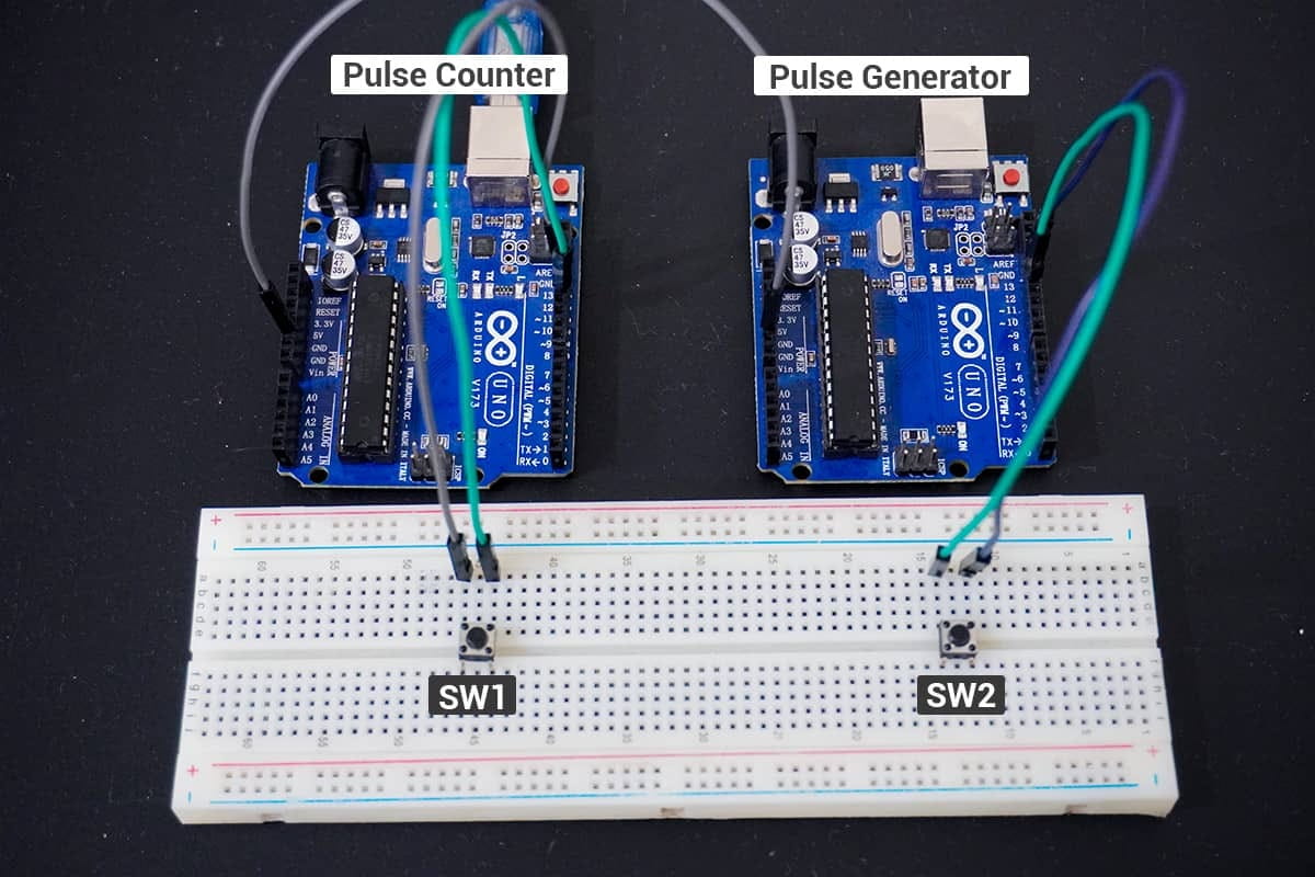
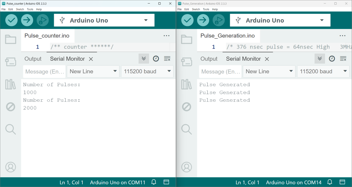
Output
Hardware Setup of Pulse counter(one Arduino UNO) and Pulse Generator( another Arduino UNO)
Serial Monitor Output
Video