I2C Quick Reference Guide
I2C Basics
Two-wire communication protocol(Serial-synchronous)
- SDA (Serial Data Line) – Bidirectional data line.
- SCL (Serial Clock Line) – Clock signal generated by the master.
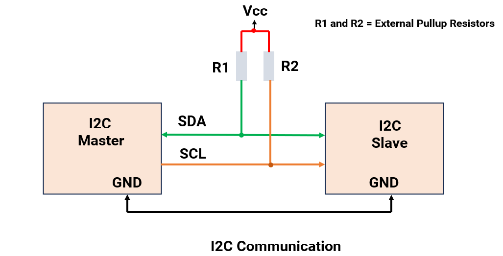
The master initiates communication always.
It is a Short-distance communication protocol with a distance of <10cm.
With I²C, multi-master and multi-slave or both at the same time are possible.
I²C communication is commonly used to interface such as LCDs, OLED displays, RTC modules, and various sensors.
I²C Communication
I²C Frame
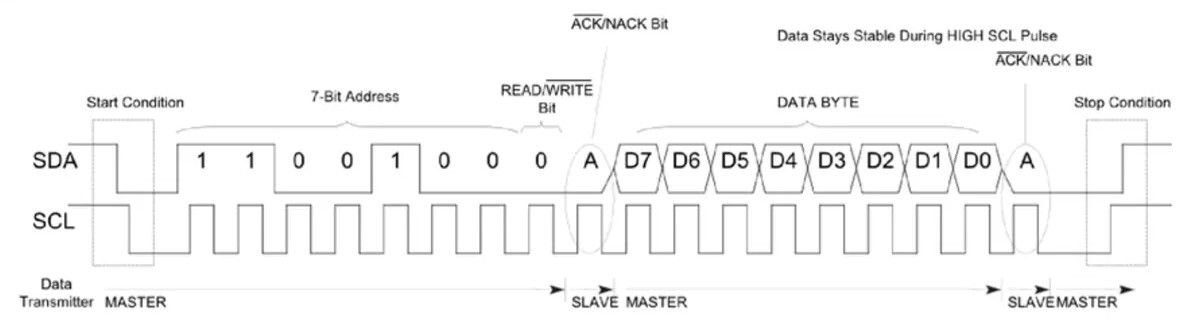
I²C Frame Description
| Frame | Description |
|---|---|
| Star Condition | SCL = HIGH, SDA = HIGH → LOW |
| 7-Bit Address | Slave address sent by master (7 bits). |
| Read/ Write bit | 0 = Write to slave 1 = Read from slave |
| ACK/NACK bit | 0 = ACK (address received) 1 = NACK (Not received) |
| Data Byte | 8 bits of data (read/write). |
| ACK/NACK bit | 0 = ACK (Data received) 1 = NACK (Data not Received) |
| Stop Condition | SCL = HIGH, SDA = LOW → HIGH (End of Communication) |
Note: SDA never changes when SCL is HIGH. If it changes, it will be either a start or stop condition.
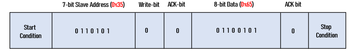
Example frames
1.I²C master writing data (0x65) to slave (address = 0x35)
2. I²C master reading data (0x66) from slave (address = 0x08)
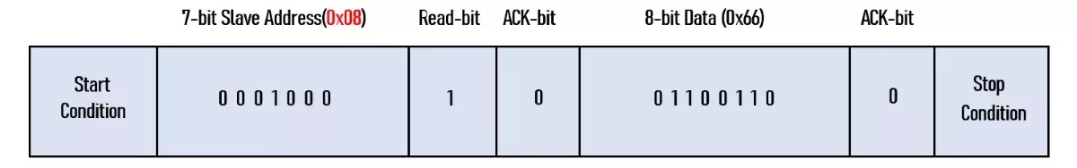
Note: 1) Data direction → MSB to LSB (MSB 1st)
2) The ideal state of SCL and SDA is HIGH.
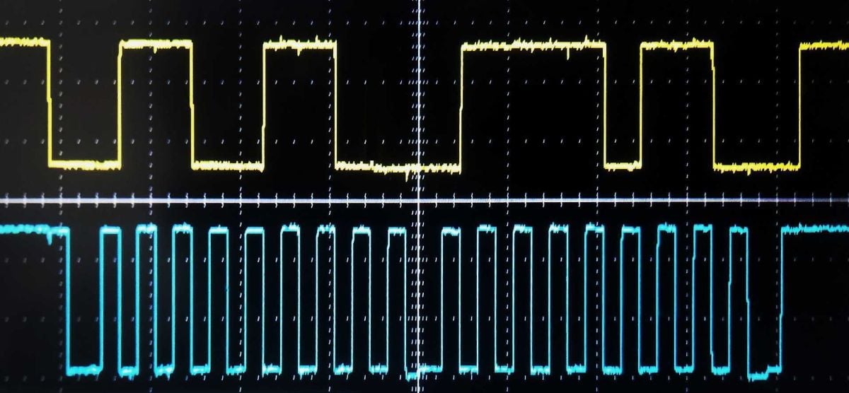
3. DSO output of I²C master sending 0x7B to slave at address 0x33.
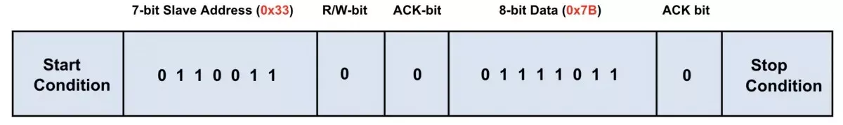
DSO Output
Pull-up in I²C Communication
- SDA and SCL use open-drain connections.
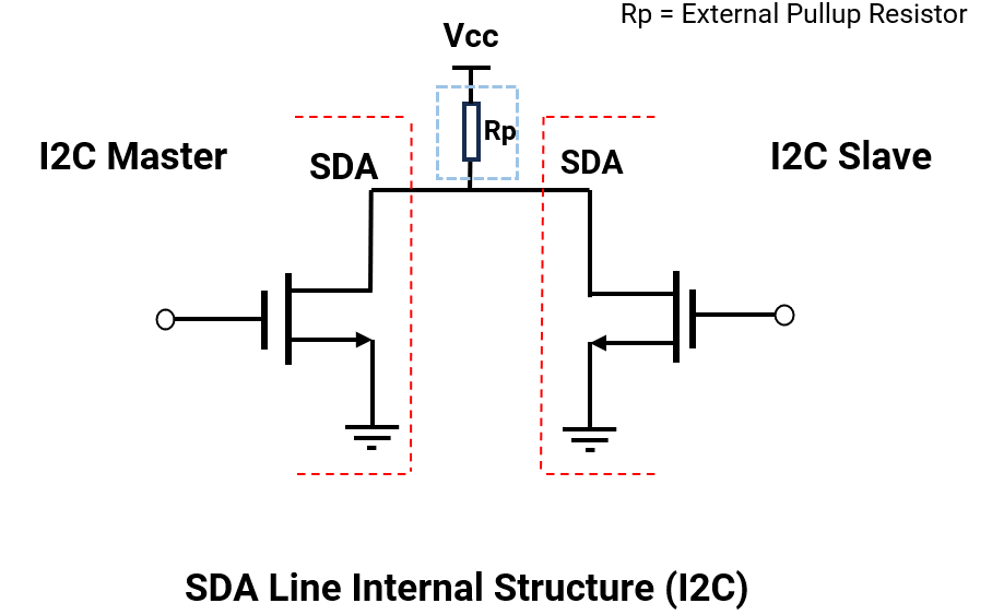
- Open drain Output→ I²C devices can only pull the bus LOW. They cannot drive HIGH actively.
- To pull the line High actively → An Internal / External Pull-up needs to be used. Without it, the bus floats and gives garbage data.
- Pull-up resistor can be from 1kΩ to 10kΩ. For long distances or high speeds, use a lower value resistor.
I²C Modes
I²C modes are defined based on communication speed. Most of the sensors come with only the standard mode.
| Modes | Maximum Bit Rate |
|---|---|
| Standard Mode | 100 kbps |
| Fast Mode | 400 kbps |
| Fast Mode Plus | 1 Mbps |
| High-Speed Mode | 3.4 Mbps |
| Ultra-Fast-Mode | 5 Mbps |
I²C Addressing (7-bit Address)
Generally, addresses from 0x00 to 0x07 are reserved for special purposes.
Address (0x00): It is used to broadcast a message sent to all slave devices, known as a General Call.
I²C Clock Stretching
A slave device can pause communication by holding the SCL clock line LOW to force the master to wait.
Gives slaves time to:
- Process received data
- Prepare data to send
I²C Voltage Level Mismatch
Mixed voltages (e.g., 3.3V MCU ↔ 5V sensor) can result in invalid logic levels and can damage devices (overvoltage on I/O pins).
To avoid this, a bidirectional level shifter or I²C buffer with voltage translation can be used.
I²C Arbitration
In multi-master I²C, when both masters try to initiate communication at the same time instance, then the master that transmits a ZERO (LOW ) bit first gets control of the I²C bus.
Why: Since the Master transmitting ZERO (LOW) will force the SDA line to LOW, although the other master tries to send ONE (HIGH).
Example
Master 1: 0xB2 → 10110010
Master 2: 0xB4 → 10110100
Bus matches for 5 bits, at bit-6, master-1 wins and continues.
(Note : In I2C on data line, transmission starts with MSB first.)
I²C in Micro-Controllers
As an important on-board communication protocol, I²C is always present in most of the controllers, i.e., AVR, PIC, ARM, and RISC.
Generally following registers are present in controllers. (with reference to AVR ATmega 328P- also known as TWI (Two-Wire Interface)).
| Registers | Description |
|---|---|
| TWBR | I²C Bit Rate Register: sets the I²C clock frequency |
| TWCR | I²C Control Register: manages interrupts, enables the interface, and controls acknowledgment and start/stop conditions. |
| TWSR | I²C Status Register: Stores the status code of the I²C (TWI) bus after each operation, sets the clock divider for I²C. |
| TWDR | I²C Data buffer: holds the data to be transmitted or the data received via I²C (TWI) |
| TWAR | I²C Address Register: stores the slave address, enables response to general call address. |
Writing I²C Driver (Master- Writing Data to slave)
- Set Bitrate - Set the prescaler and desired I²C bitrate.
- Send Start Condition - Set the bits in the control register to initiate the start condition.
- Wait for TWI0NT- wait for action to perform.
- Send Slave Address + Write Bit .
- Wait for TWINT - wait for action to perform
- Send a Data Byte to the slave.
- Wait for TWINT -wait for action to perform.
- Send Stop Condition - Stop I²C & bus release.
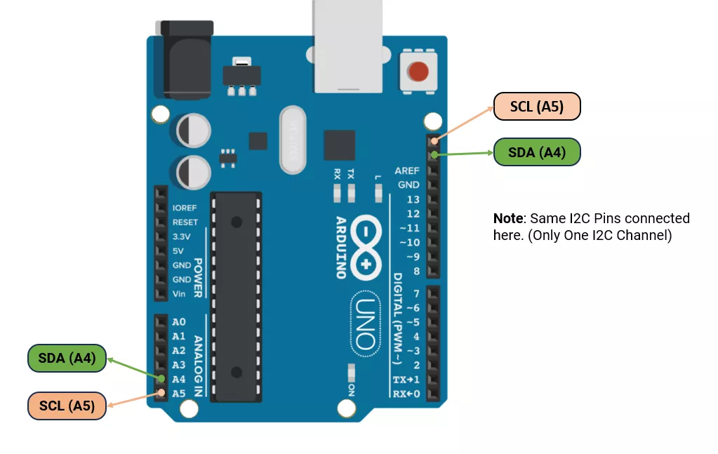
I²C in Arduino Uno (ATmega328P)
I²C communication pins in Arduino UNO
Arduino I²C (Wire Library) Functions
In Arduino UNO, the Wire.h library is used for I²C.
The default speed is 100 kHz, but it can be changed to 400 kHz.
| Function | Description |
|---|---|
Wire.begin() | Initialize I²C as master |
Wire.begin(address) | Initialize I²C as slave with address |
Wire.setClock(frequency) | Set I²C speed (Hz) |
Wire.beginTransmission(address) | Start communication with a slave device |
Wire.write(data) | Send data to buffer. |
Wire.endTransmission() | Ends transmission started by beginTransmission() and sends all queued bytes to the device. |
Wire.requestFrom(address, len) | Request bytes from a slave |
Wire.available() | Check if data is received |
Wire.read() | Read received byte |
Wire.onReceive(handler) | Set callback for received data |
Wire.onRequest(handler) | Set callback for data requests |
Example
Send character ‘A’ from master( Arduino UNO) to slave 0x08 (Arduino UNO) after every 1 second.
Master Code
#include <Wire.h>
void setup() {
  Wire.begin(); // Initialize  I²C as master
}
void loop() {
  Wire.beginTransmission(0x08);  // Slave address 0x08
  Wire.write('A'); // Send character
  Wire.endTransmission();
  delay(1000);
}
Slave Code
#include <Wire.h>
void setup() {
  Serial.begin(9600); // initialize the serial communication
  Wire.begin(0x08);  // Initialize I2C in slave mode
  Wire.onReceive(receiveEvent);  // Register callback
}
void loop() {
}
// Callback function definition
void receiveEvent(int bytesReceived) {
  if (Wire.available()) {
    char receiveData = Wire.read(); // read the received data from master
    // display data received from master
    Serial.print(receiveData);
  }
}
Concept understood? Let's apply and learn for real