20. LEDs Fading Speed Control
We need to make five LEDs fade in opposite phases (some brighten while others dim), with the fade speed controlled by a potentiometer.
So we have to interface a potentiometer and five LEDs with a microcontroller.
Potentiometer & LED Interfacing
Potentiometer Interfacing
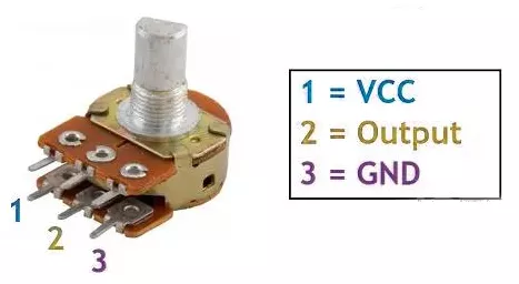
- Connection: Connect the potentiometer terminals 1 and 3 to VCC and GND or vice versa. Terminal 2 (wiper) to the MCU ADC pin.
Note: We can use any of the potentiometers with values between 1kΩ and 10kΩ.
Five LEDs Interfacing
Connect each PWM GPIO pin to an anode of a separate LED, and the cathode of each LED to GND with a current-limiting resistor in series to protect LEDs and GPIO pins.
Calculating the current-limited Resistor Value
Case 1: 5V Supply
- LED forward voltage (Vf) = 1.8V (from datasheet)
- Voltage across resistor (VR) = Supply voltage – Vf = 5V – 1.8V = 3.2V
- Resistor value (R) = VR / I = 3.2V / 10 mA = 320 Ω
Standard resistor values near 320 Ω: 330 Ω or 300 Ω (whichever is available).
Similarly, Case 2: 3.3V Supply
- Voltage across resistor (VR) = 3.3V – 1.8V = 1.5V
- Resistor value (R) = 1.5V / 10 mA = 150 Ω
Standard resistor value: 150 Ω.
So, by selecting a proper resistor, LED, and potentiometer connections, we can implement the task.
Below are the solutions to the given task using different microcontrollers
- STM32
- ESP32
- Arduino UNO
We’re using an STM32 NUCLEO-F103RB board, which runs at a 3.3V logic level.
Key Peripherals Used
- ADC1 Channel 0 (PA0): Reads the analog voltage from the potentiometer.
- TIM1 for PWM on channels 1, 2, and 3 (PA8, PA9, PA10).
- TIM3 for PWM on channels 1 and 2 (PA6, PA7).
- TIM4: Configured as a basic timer generating periodic interrupts to trigger ADC conversions and adjust LED fading speed dynamically via the potentiometer reading.
- GPIO: PA8, PA9, PA10, PA6, and PA7 are configured as alternate function pins for PWM output.
- Optional USART2: Used for serial debugging (configured but not used here).
STM32 Hardware Connection
- Potentiometer Setup:
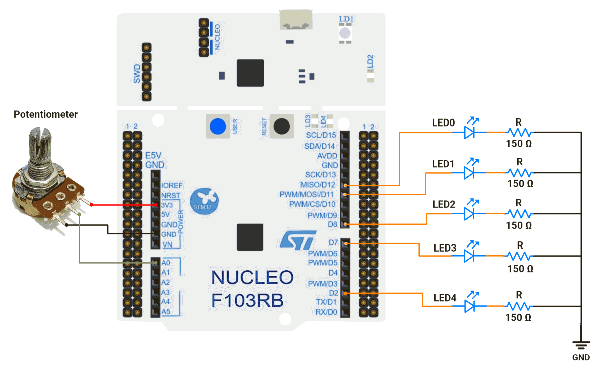
- Connect the potentiometer’s middle pin to PA0 (ADC1_IN0) for analog input.
- Connect the other two pins to 3.3V (VCC) and GND to create a voltage divider.
- Use a 10kΩ potentiometer for best results.
- LED Setup:
- PWM Output Pin: PA8 (TIM1 Channel 1).
- Connect the LED anode (long leg) to PA8.
- Connect the LED cathode (short leg) to GND through a 150Ω resistor.
- Repeat similar connections for PA9, PA10, PA6, and PA7.
Circuit Diagram
STM32 Firmware Implementation
Project Setup in STM32CubeIDE:
- Create a Project
- Open STM32CubeIDE, start a new project, and select the NUCLEO-F103RB board.
- Basic Configuration (via CubeMX inside CubeIDE)
- Clock: Use the default HSI oscillator with PLL enabled (configured in
SystemClock_Config). - GPIO:
- GPIO clocks enabled for PORTA, PORTB, PORTC, PORTD.
- GPIO pins for ADC input (PA0) and PWM output pins are auto-configured via CubeMX.
- ADC1 (Analog Input Source):
- Resolution: 12-bit (0–4095 range).
- Conversion mode: Single, software-triggered.
- Channel: ADC_CHANNEL_0 (PA0).
- Timer 1 (TIM1 – PWM Generator):
- Prescaler = 0 → Timer clock = APB2.
- Period (ARR) = 255
- PWM Mode 1 enabled on Channels 1, 2, and 3.
- Timer 3 (TIM3 – PWM Generator):
- Prescaler = 0.
- Period (ARR) = 255.
- PWM Mode 1 enabled on Channels 1 and 2.
- Timer 4 (TIM4 – Basic Timer):
- Mode: Basic Timer with internal clock.
- Prescaler = 100.
- Period (ARR) = 8000.
- Update Event Interrupt enabled in NVIC settings.
- This interrupt periodically triggers ADC readings.
- Also controls the PWM fading speed dynamically.
- USART2: Enabled at 115200 baud, 8-N-1, for debugging/expansion if needed.
- Clock: Use the default HSI oscillator with PLL enabled (configured in
- Code Generation
- CubeMX will automatically generate all the startup code, including:
HAL_Init()→ Initializes the HAL library.SystemClock_Config()→ Configures HSI + PLL system clock.MX_GPIO_Init()→ Initializes all GPIO ports.MX_ADC1_Init()→ Configures ADC1 for analog input.MX_TIM1_Init()→ Configures TIM1 for PWM output.MX_TIM3_Init()→ Configures TIM3 for PWM output.MX_TIM4_Init()→ Configures TIM4 as basic timerMX_USART2_UART_Init()→ Initializes UART2 for debugging.
- This code sets up the hardware and prepares the project for firmware development, so we only need to add our application logic in the user code sections
- CubeMX will automatically generate all the startup code, including:
Code Snippets from main.c
ADC Initialization (MX_ADC1_Init):
hadc1.Instance = ADC1;
hadc1.Init.ScanConvMode = ADC_SCAN_DISABLE;
hadc1.Init.ContinuousConvMode = DISABLE;
hadc1.Init.DataAlign = ADC_DATAALIGN_RIGHT;
This configures ADC1 for single-channel operation with right-aligned 12-bit results.
Timer Initialization (MX_TIM1_Init, MX_TIM3_Init, and MX_TIM4_Init):
TIM1 and TIm3
htim1.Init.Period = 255;  // ARR register value
htim1.Init.Prescaler = 0;  // No prescaling
sConfigOC.OCMode = TIM_OCMODE_PWM1;  // PWM Mode 1

//Similar configuration is applied for TIM3 as well.
These functions configure timers for PWM generation.
TIM4
 htim4.Instance = TIM4;
  htim4.Init.Prescaler = 100;
  htim4.Init.CounterMode = TIM_COUNTERMODE_UP;
  htim4.Init.Period = 8000;
  htim4.Init.ClockDivision = TIM_CLOCKDIVISION_DIV1;
  htim4.Init.AutoReloadPreload = TIM_AUTORELOAD_PRELOAD_DISABLE;
  if (HAL_TIM_Base_Init(&htim4) != HAL_OK)
  {
    Error_Handler();
  }
  sClockSourceConfig.ClockSource = TIM_CLOCKSOURCE_INTERNAL;
  if (HAL_TIM_ConfigClockSource(&htim4, &sClockSourceConfig) != HAL_OK)
  {
    Error_Handler();
  }
  sMasterConfig.MasterOutputTrigger = TIM_TRGO_RESET;
  sMasterConfig.MasterSlaveMode = TIM_MASTERSLAVEMODE_DISABLE;
  if (HAL_TIMEx_MasterConfigSynchronization(&htim4, &sMasterConfig) != HAL_OK)
  {
    Error_Handler();
  }
These functions configure TIM4 as a basic up-counter with an internal clock, prescaler 100, period 8000, and update interrupt for periodic ADC triggering and PWM fading control.
Macros Definition:
The provided code defines timer handles and channel mappings for cleaner code organization:
// Define timer handles and channels for each LED
#define LED0_TIMER &htim3
#define LED0_TIMER_CHANNEL TIM_CHANNEL_1

#define LED1_TIMER &htim3
#define LED1_TIMER_CHANNEL TIM_CHANNEL_2

#define LED2_TIMER &htim1
#define LED2_TIMER_CHANNEL TIM_CHANNEL_2

#define LED3_TIMER &htim1
#define LED3_TIMER_CHANNEL TIM_CHANNEL_1

#define LED4_TIMER &htim1
#define LED4_TIMER_CHANNEL TIM_CHANNEL_3

// ADC value range (12-bit ADC)
#define ADC_MIN_VALUE 0
#define ADC_MAX_VALUE 4095

// PWM duty cycle range
#define PWM_MIN_DUTY_CYCLE 0
#define PWM_MAX_DUTY_CYCLE 255
Custom Mapping Function:
The mapValue() function provides linear interpolation between ranges:
uint16_t mapValue(uint16_t x, uint16_t inMin, uint16_t inMax,
                  uint16_t outMin, uint16_t outMax) {
    return (x - inMin) * (outMax - outMin) / (inMax - inMin) + outMin;
}
TIM4 interrupt handling (HAL_TIM_PeriodElapsedCallback)
// Period elapsed callback
void HAL_TIM_PeriodElapsedCallback(TIM_HandleTypeDef *htim) {
   if (htim->Instance == TIM4) {
       // Start ADC conversion and wait for the result
       HAL_ADC_Start(&hadc1);
       HAL_ADC_PollForConversion(&hadc1, 20);
       g_adcValue = HAL_ADC_GetValue(&hadc1);
       // Map ADC value to PWM range for LED1 brightness
       g_fadeDelay = mapValue(g_adcValue, ADC_MIN_VALUE, ADC_MAX_VALUE, 1, 15);
   }
}
This function executes whenever timer TIM4 overflows, triggering an interrupt. It reads the current potentiometer value via the ADC, then maps this reading to a delay value (g_fadeDelay) between 1 and 15 milliseconds, which adjusts the LED fading speed dynamically.
PWM Initialization in main():
Before the while loop, PWM channels are enabled:
 HAL_TIM_PWM_Start(LED0_TIMER, LED0_TIMER_CHANNEL);
 HAL_TIM_PWM_Start(LED1_TIMER, LED1_TIMER_CHANNEL);
// Start remaining PWM channels…
Main Control Loop:
while (1) {
  // Fade in all odd-numbered LEDs while fading out even-numbered LEDs
  for (int i = PWM_MIN_DUTY_CYCLE; i <= PWM_MAX_DUTY_CYCLE; i += 1) {
    // Set PWM duty cycle for each LED
    // LED0, LED2, LED4 fade in (increasing brightness)
    __HAL_TIM_SET_COMPARE(LED0_TIMER, LED0_TIMER_CHANNEL, i);
    __HAL_TIM_SET_COMPARE(LED2_TIMER, LED2_TIMER_CHANNEL, i);
    __HAL_TIM_SET_COMPARE(LED4_TIMER, LED4_TIMER_CHANNEL, i);

    // LED1 and LED3 fade out (decreasing brightness)
    __HAL_TIM_SET_COMPARE(LED1_TIMER, LED1_TIMER_CHANNEL, PWM_MAX_DUTY_CYCLE - i);
    __HAL_TIM_SET_COMPARE(LED3_TIMER, LED3_TIMER_CHANNEL, PWM_MAX_DUTY_CYCLE - i);

    // Delay based on ADC reading (controls fade speed)
    HAL_Delay(g_fadeDelay);
  }

  // Pause for some time
  HAL_Delay(10 * g_fadeDelay);

  // Fade out all odd-numbered LEDs while fading in even-numbered LEDs
  for (int i = PWM_MAX_DUTY_CYCLE; i >= PWM_MIN_DUTY_CYCLE; i -= 1) {
    // Set PWM duty cycle for each LED
    // LED0, LED2, LED4 fade out (decreasing brightness)
    __HAL_TIM_SET_COMPARE(LED0_TIMER, LED0_TIMER_CHANNEL, i);
    __HAL_TIM_SET_COMPARE(LED2_TIMER, LED2_TIMER_CHANNEL, i);
    __HAL_TIM_SET_COMPARE(LED4_TIMER, LED4_TIMER_CHANNEL, i);

    // LED1 and LED3 fade in (increasing brightness)
    __HAL_TIM_SET_COMPARE(LED1_TIMER, LED1_TIMER_CHANNEL, PWM_MAX_DUTY_CYCLE - i);
    __HAL_TIM_SET_COMPARE(LED3_TIMER, LED3_TIMER_CHANNEL, PWM_MAX_DUTY_CYCLE - i);

    // Delay based on ADC reading (controls fade speed)
    HAL_Delay(g_fadeDelay);
  }

  // Pause for some time
  HAL_Delay(10 * g_fadeDelay);
}
LED Control Logic Explanation:
- The STM32 continuously reads the potentiometer position via a 12-bit ADC (0 to 4095). This value is mapped to a small delay range (1 to 15 ms) that controls how fast the LEDs fade.
- Five LEDs are grouped into two sets: even-numbered LEDs fade in while odd-numbered LEDs fade out, then they reverse roles. PWM duty cycles (0 to 255) control the brightness of each LED accordingly.
- The fading loops run in real time, using delay values derived from the potentiometer to dynamically adjust the smooth alternating breathing effect.
Download Project
The complete STM32CubeIDE project (including .ioc configuration, main.c, and HAL files) is available here:
We are using the ESP32 DevKit v4 development board and programming it using the Arduino IDE.
- Before uploading, make sure to select “ESP32 Dev Module” as the board to ensure correct settings and compatibility.
LEDC (LED Controller) peripheral is a dedicated hardware PWM controller, optimized for applications like LED brightness control using PWM, and we will use it in this task.
Pins to Avoid for PWM on ESP32
- GPIO6–11 → Used for flash memory
- GPIO34–39 → Input-only pins (not suitable for PWM output)
- GPIO0, GPIO2, GPIO15 → Strapping pins (affect boot mode)
- EN, SENSOR_VP, SENSOR_VN → Reserved for special functions
Important Note
In Arduino Core v2.x or below for ESP32, LEDC API functions like ledcSetup() and ledcAttachPin() are used for PWM configuration.
In Arduino Core v3.x, these functions are removed to avoid compilation errors; use the updated LEDC API instead; otherwise, you will encounter a compilation error. e.g.:
ledcAttach(pin, freq, resolution);ledcWrite(channel, dutyCycle);
Reference: ESP32 Arduino Core 2.x → 3.0 Migration Guide
STM32 Circuit Connection
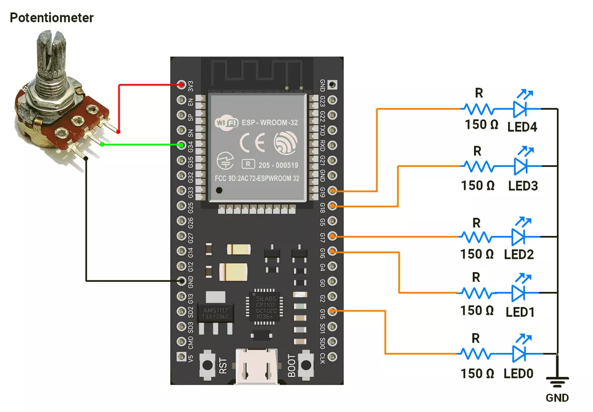
- Connect the LEDs to GPIO pins 15, 16, 17, 18, and 19 with a 150 Ω resistor.
- Connect the potentiometer to the GPIO pin 34.
Circuit Diagram
ESP32 Firmware Implementation
After analyzing the task as shown in the GIF.
We observed the following points:
LED Grouping:
- LEDs are divided into two groups:
- Group 1: LEDs with even numbers (LED0, LED2, LED4).
- Group 2: LEDs with odd numbers (LED1, LED3).
- When the Group 1 LEDs are fading in, Group 2 LEDs will fade out and vice versa.
Fade Timing:
- ADC values (0–4095) are mapped to a delay range (10–1000 µs) for PWM control.
- The delay between each PWM step increases as the potentiometer value increases.
- The total duration of the fade-in/out is:
- Minimum duration: 40.95 ms (4095 steps * 10 µs delay).
- Maximum duration: 4.095 sec (4095 steps * 1000 µs delay).
- The fade duration depends on the potentiometer position, changing from 0% to 100%.
Code
//   Hardware Configuration
#define POT_PIN 34  // Potentiometer connected to GPIO15 (ADC input pin)

#define ADC_RESOLUTION 12U   // ADC resolution = 12-bit → values from 0 to 4095
#define PWM_RESOLUTION 12U   // PWM resolution = 12-bit → duty cycle 0–4095
#define ADC_MAX_VALUE 4095U  // Maximum ADC value for 12-bit
#define PWM_MAX_VALUE 4095U  // Maximum PWM value for 12-bit
#define MAX_DELAY 1000U      // Maximum fade delay (slower fading)
#define MIN_DELAY 10U        // Minimum fade delay (faster fading)

const int led_pins[] = { 15, 16, 17, 18, 19 };  // Array of LED pins (must support PWM)
uint16_t potValue = 0;                          // Variable to store potentiometer reading

//   Setup Function
void setup() {
  // Attach PWM functionality to each LED pin
  // Frequency = 1 kHz, Resolution = 12-bit
  for (uint8_t i = 0; i < 5; i++) {
    ledcAttach(led_pins[i], 1000, PWM_RESOLUTION);
    ledcWrite(led_pins[i], 0);  // Start with LEDs OFF
  }

  // Configure ADC resolution for potentiometer input
  analogReadResolution(ADC_RESOLUTION);

  // Initialize serial monitor for debugging
  Serial.begin(115200);
}

//   Loop Function
void loop() {
  // 1. Read potentiometer value (0–4095)
  potValue = analogRead(POT_PIN);

  // 2. Map potentiometer value to delay (10–1000 µs)
  // This controls how FAST or SLOW the LEDs fade
  uint16_t fadeDelay = map(potValue, 0, ADC_MAX_VALUE, MIN_DELAY, MAX_DELAY);
  Serial.println(fadeDelay);  // Debugging: print fade speed

  // 3. FADE IN sequence (LEDs gradually increase brightness)
  for (uint16_t brightness = 0; brightness <= PWM_MAX_VALUE; brightness++) {
    // LED behavior:
    ledcWrite(led_pins[0], brightness);                  // LED 0: fade in
    ledcWrite(led_pins[1], PWM_MAX_VALUE - brightness);  // LED 1: fade out
    ledcWrite(led_pins[2], brightness);                  // LED 2: fade in
    ledcWrite(led_pins[3], PWM_MAX_VALUE - brightness);  // LED 3: fade out
    ledcWrite(led_pins[4], brightness);                  // LED 4: fade in

    // Apply delay based on potentiometer position
    delayMicroseconds(fadeDelay);
  }

  // Hold LEDs at max brightness before fading out
  delayMicroseconds(1500 * fadeDelay);

  // 4. FADE OUT sequence (LEDs gradually decrease brightness)
  for (uint16_t brightness = PWM_MAX_VALUE; brightness > 0; brightness--) {
    // LED behavior:
    ledcWrite(led_pins[0], brightness);                  // LED 0: fade out
    ledcWrite(led_pins[1], PWM_MAX_VALUE - brightness);  // LED 1: fade in
    ledcWrite(led_pins[2], brightness);                  // LED 2: fade out
    ledcWrite(led_pins[3], PWM_MAX_VALUE - brightness);  // LED 3: fade in
    ledcWrite(led_pins[4], brightness);                  // LED 4: fade out

    // Apply delay based on potentiometer position
    delayMicroseconds(fadeDelay);
  }

  // Hold LEDs at minimum brightness before next cycle
  delayMicroseconds(1500 * fadeDelay);
}
Code Explanation
- The ADC value from GPIO pin 34 (0–4095) is mapped to a fade delay of 10 to 1000 µs per step.
- Fade In: LEDs brighten or dim alternately using
ledcWrite()in a loop. - Fade Out: LEDs reverse the pattern in another loop.
- Add delays for smooth transitions and visibility.
We are using the Arduino UNO development board and programming it using the Arduino IDE.
- Before uploading, make sure to select “Arduino UNO” as the board to ensure correct settings and compatibility.
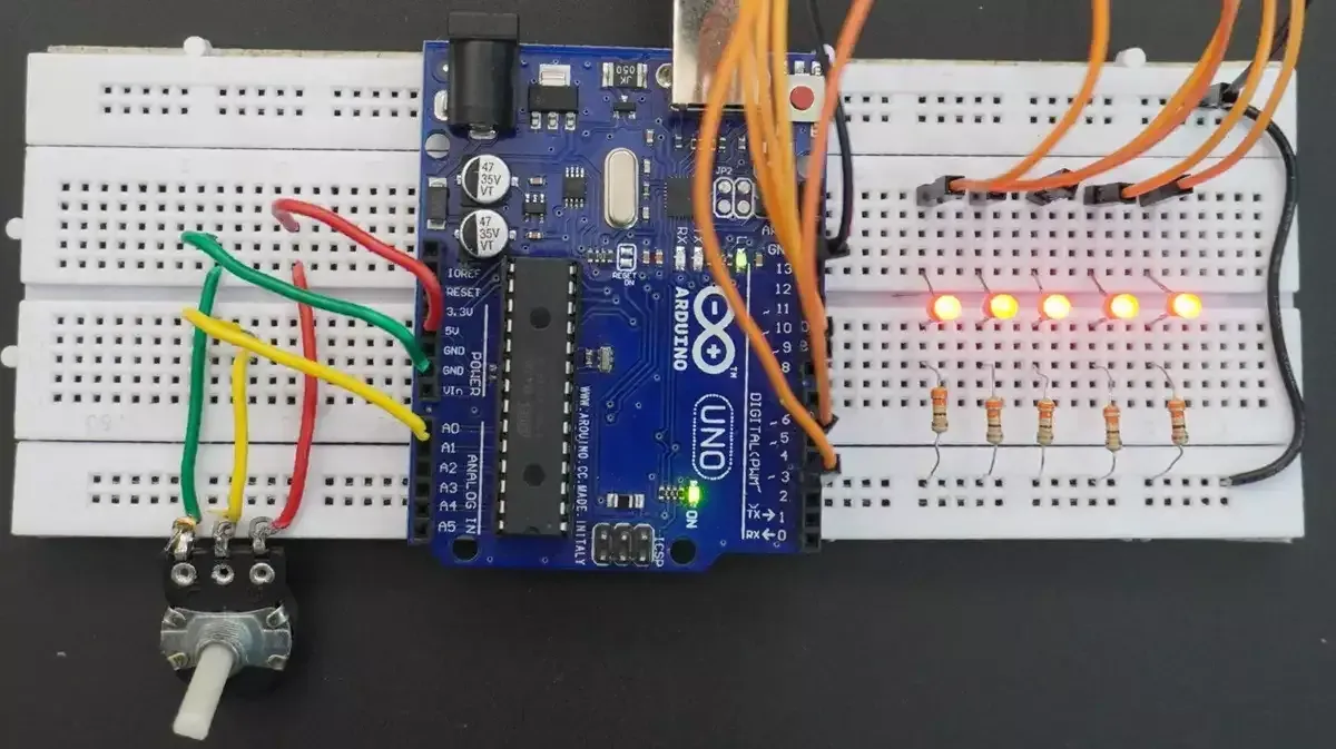
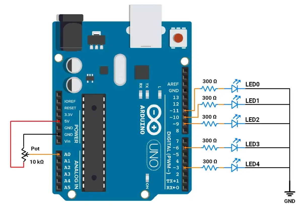
The LEDs are connected to an Arduino UNO
In Arduino UNO, the PWM signal is generated using the analogWrite().
It has 6 PWM pins (3, 5, 6, 9, 10, 11) with 8-bit resolution (0–255) and fixed frequencies of ~490 Hz or ~976 Hz.
Arduino UNO Circuit connection
Arduino UNO Firmware Implementation
After analyzing the task as shown in the GIF.
We observed the following points:
LED Grouping:
- LEDs are divided into two groups:
- Group 1: LEDs with even numbers (LED0, LED2, LED4).
- Group 2: LEDs with odd numbers (LED1, LED3).
- When the Group 1 LEDs are fading in, Group 2 LEDs will fade out and vice versa.
Fade Timing:
- ADC values (0–1023) are mapped to a delay range (1–10 ms) for PWM control.
- The delay between each PWM step increases as the potentiometer value increases.
- The total duration of the fade-in/out is:
- Minimum duration: 255 ms (255 steps * 1 ms delay).
- Maximum duration: 2550 ms (255 steps * 10 ms delay).
- The fade duration depends on the potentiometer position, changing from 0% to 100%.
Code
const int ledPins[] = { 11, 10, 9, 6, 3 };  // PWM pins for LEDs
int potValue = 0;                           // Variable to store potentiometer reading

void setup() {
  // Set all LED pins as output
  for (int i = 0; i < 5; i++) {
    pinMode(ledPins[i], OUTPUT);  // Configuring LED pins for output
  }
}

void loop() {
  // Read the potentiometer value from A0 (range: 0–1023)
  potValue = analogRead(A0);

  // Map potentiometer value (0–1023) to delay range (1–10 ms)
  // This controls how fast the LEDs fade in and out
  int fadeDelay = map(potValue, 0, 1023, 1, 10);

  // Gradually increase brightness (fade in)
  for (int brightness = 0; brightness <= 255; brightness++) {
    // Adjust the brightness of each LED:
    analogWrite(ledPins[0], brightness);        // LED 0: fade in (brightness increases)
    analogWrite(ledPins[1], 255 - brightness);  // LED 1: fade out (brightness decreases)
    analogWrite(ledPins[2], brightness);        // LED 2: fade in (brightness increases)
    analogWrite(ledPins[3], 255 - brightness);  // LED 3: fade out (brightness decreases)
    analogWrite(ledPins[4], brightness);        // LED 4: fade in (brightness increases)
    delay(fadeDelay);                           // Add delay to control the speed of fading
  }

  // Add a delay after the fade-in sequence for visibility
  delay(100 * fadeDelay);

  // Gradually decrease brightness (fade out)
  for (int brightness = 255; brightness >= 0; brightness--) {
    // Adjust the brightness of each LED:
    analogWrite(ledPins[0], brightness);        // LED 0: fade out (brightness decreases)
    analogWrite(ledPins[1], 255 - brightness);  // LED 1: fade in (brightness increases)
    analogWrite(ledPins[2], brightness);        // LED 2: fade out (brightness decreases)
    analogWrite(ledPins[3], 255 - brightness);  // LED 3: fade in (brightness increases)
    analogWrite(ledPins[4], brightness);        // LED 4: fade out (brightness decreases)
    delay(fadeDelay);                           // Add delay to control the speed of fading
  }

  // Add a delay after the fade-out sequence for visibility
  delay(100 * fadeDelay);
}
Code Explanation
- The ADC value from A0 (0–1023) is mapped to a fade delay of 1–10 ms per step.
- Fade In: LEDs brighten (brightness) or dim (255-brightness) alternately using
analogWrite()in a loop. - Fade Out: LEDs reverse the pattern in another loop.
- Add delays for smooth transitions and visibility.
Output