21. PWM High-Frequency Generation
There is a DC motor that requires a PWM frequency between 5 to 10 kHz to drive it. Low PWM frequency generates noise while driving the motor.
So,
- Generate a PWM with any frequency between 5 to 10 kHz using a microcontroller.
- Control the PWM duty cycle using a potentiometer to adjust the motor's speed.
Note: If you don’t have DSO to analyze the output PWM frequency, you can use simulation tools like Proteus, Wokwi, or any other platform.
What is PWM?
PWM (Pulse Width Modulation) is varying the pulse width to control the amount of power delivered.

PWM is used for dimming LEDs, controlling motor speed, and generating sounds like beeps in a buzzer.
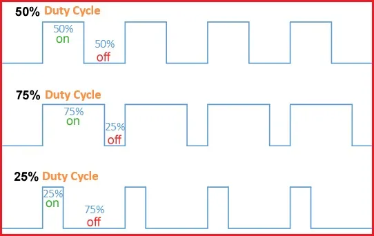
Duty Cycle
The percentage of time the signal is "ON" during one cycle.
- 40% duty cycle → 40% ON time, 60% OFF time.
Duty Cycle (%) = (Time ON / Total Period) × 100
- Time ON = duration the signal stays high.
- Total Period = total duration of one complete cycle (Time ON + Time OFF).
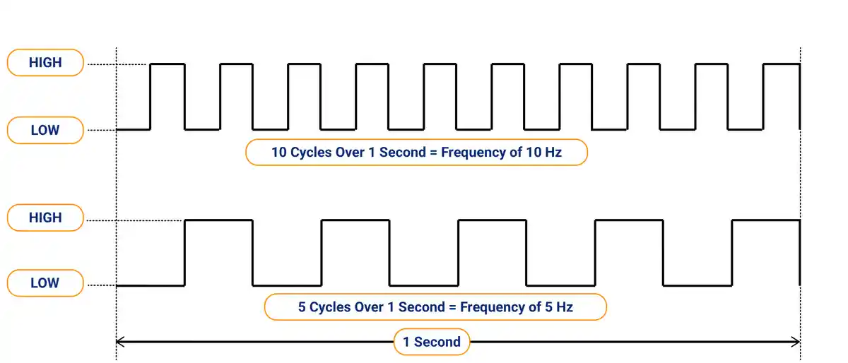
Frequency
The number of cycles (Time ON + Time OFF) per second. It is measured in Hertz (Hz).
If the PWM frequency is too low, the human eye can detect the LED flickering as it turns ON and OFF.
Thus, use PWM frequency >100 Hz to avoid flicker, but 500 Hz–5 kHz for high-power LEDs.
Similarly, in motor, for smoother motion 1–20 kHz, but adjust based on motor type and driver limits.
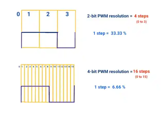
Resolution
PWM resolution refers to the number of discrete steps (levels) available to adjust the duty cycle of a PWM signal.
For example:
- A 2-bit PWM has 4 levels (0 to 3) (calculated as 2^bits = 2^2=4)
- Duty cycle change per step = 100 / (no. of steps -1) = 100 / (4-1) = 33.33 %
- A 4-bit PWM has 16 levels (0 to 15)
- A 10-bit PWM has 1024 levels (0 to 1023)
| Bits (n) | Resolution (Steps) | Duty Cycle change per step ( % ) |
|---|---|---|
| 1 bit | 2^1=2 (0 ,1 ) | 100% / 1 = 100% |
| 2 bits | 2^2=4 (0 to 3) | 100% / 3 = 33.33% |
| 4 bits | 2^4=16 (0 to 15) | 100% / 15 = 6.66% |
| 16 bits | 2^16 = 65,536 | 100% / 65535 ≈ 0.0015% |
Why Resolution Matters?
Resolution defines how finely you can control the output.
Dithering
Dithering in PWM is the technique of rapidly toggling between different duty cycles for smoother analog output.
If you want a duty cycle of 12.5%, but PWM can only do 12% or 13%. Dithering alternates between these values:
cycle 1: 12%
cycle 2: 13%
cycle 3: 12%
cycle 4: 13%
This averages out to 12.5% over time.
PWM Modes
- Fast PWM
Fast PWM is commonly used for basic applications like LED dimming or motor control. It offers faster updates, which can result in smoother control but may introduce more ripple and noise - Phase Correct PWM
Phase Correct PWM is preferred in applications that require balanced and stable signals, such as audio or precision motor control. It produces symmetric output with less distortion and reduced harmonics, but updates more slowly.
PWM Registers
Considering AVR microcontrollers
| Register | Purpose |
| TCCRnA | Select PWM mode and compare output behavior. |
| TCCRnB | Sets clock source and prescaler. |
| OCRnx | Sets the PWM duty cycle (compare value). |
| ICRn | Used to set TOP value in some modes (like Fast PWM with ICRn). |
| TIMSKn | Enables PWM interrupts (optional). |
Where,
n = Timer number (0, 1, or 2)
x = Channel (A or B)
NOTE: ARM and RISC-based 32-bit microcontrollers may have more PWM-related registers (like frequency control, dead time insertion, synchronized updates, etc).
PWM Driver Setup
- Set PWM mode → Configure the control registers to select the desired PWM mode. (Fast PWM, Phase Correct PWM)
- Set prescaler → Adjust the prescaler value (e.g., 1, 8, 64, 256) to set the desired frequency.
- Set Resolution → Choose a register (e.g., ICR or OCR) to define the maximum count value. Determines PWM resolution (e.g., 8-bit = 255, 10-bit = 1023)
- Set duty cycle → Write the duty cycle value to the appropriate register (e.g., OCR).
- Enable PWM Output → Configure the GPIO pin as a PWM output. Enable timer/counter and PWM output in control registers.
The hardware generates the PWM signal without CPU intervention.
Arduino function
analogWrite(pin, value)
Generates a PWM signal on the specified pin. The value ranges from 0 (0% duty cycle) to 255 (100% duty cycle).
On Arduino Uno, 6 pins can generate a PWM waveform (marked with ~):
- Pins 5 and 6 → ~980 Hz PWM frequency
- Pins 3, 9, 10, and 11 → ~490 Hz PWM frequency
These default frequencies can be changed by modifying timer settings, but doing so may affect other functions like delay() or millis().
Examples
1. LED Fade
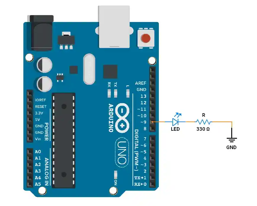
// Fade an LED using PWM
int ledPin = 9; // Pin with PWM (marked ~ on Arduino Uno)

void setup() {
  pinMode(ledPin, OUTPUT);
}

void loop() {
  // Increase brightness
  for (int brightness = 0; brightness <= 255; brightness++) {
    analogWrite(ledPin, brightness); // Set PWM duty cycle
    delay(10);
  }

  // Decrease brightness
  for (int brightness = 255; brightness >= 0; brightness--) {
    analogWrite(ledPin, brightness);
    delay(10);
  }
}
2. Changing PWM Frequency (50Hz, 7.5%)

void setup() {
  pinMode(9, OUTPUT);

  // Set Fast PWM on Timer1, change prescaler
  TCCR1A = _BV(COM1A1) | _BV(WGM11); // non-inverting mode, Fast PWM
  TCCR1B = _BV(WGM13) | _BV(WGM12) | _BV(CS11); // Prescaler 8
  ICR1 = 40000; // TOP value -> ~50Hz
  OCR1A = 3000; // Duty cycle
}

void loop(){

}