3. Multiple Drivers
Drive a single output y from two different inputs a and b using two separate continuous assignments. Observe the result when a and b differ.
Requirements:
Module Name: top_module
Inputs: a, b (1-bit each)
Outputs: y (1-bit)
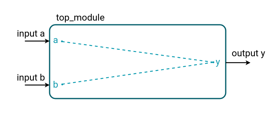
This problem is only for educational purposes to show what happens if multiple drivers drive the same wire. In real-world designs, multiple drivers on a single wire should be avoided because it causes conflicts (contention) in hardware.
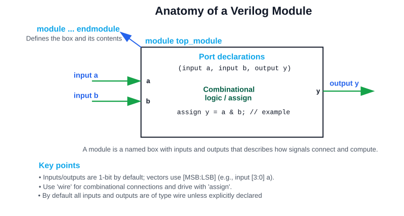
Writing Your First Verilog Module
Every design in Verilog starts with a module. A module is like a “box” with inputs and outputs that describes how signals are connected or processed.
Structure:
module module_name (
	input a, // Port declarations
	input b,
	output y
);

   // Internal signals (optional)
   wire w;

   // Logic description
   assign y = a & b;   // continuous assignment

endmodule
- module … endmodule → defines the boundaries of your design.
- Inputs: signals coming into the design.
- Outputs: signals produced by the design.
- Internal wires: connections inside the module.
- assign: continuous assignment → drives wires automatically.
Equivalent verilog code:
// Sample top_module (and gate) in verilog
module top_module(
	input a, // for all input/output default type is wire
	input b,
    output y
);
	assign y = a & b;
endmodule
Data Type - wire
- A wire represents a physical connection between components in hardware (just like a real copper wire on a circuit board
- It does not store a value → it only reflects whatever is being driven onto it
- If no one drives it, the wire’s value defaults to High-Impedance (z).
How to Use wire
- You must drive a wire using:
- A continuous assignment (assign)
- Or by connecting it to a module’s output port
Characteristics of wire
- Direction of flow: values flow into the wire from its driver(s).
- Updates instantly: whenever the right-hand side changes, the wire updates.
- No memory: unlike reg, it cannot “remember” values across time.
Multiple Drivers
- In real circuits, you can connect multiple outputs to a single wire → in Verilog too, a wire can have multiple drivers.
- If drivers conflict:
- 0 vs 1 → results in x (unknown)
- Pull-ups/pull-downs (supply0, supply1) can resolve defaults
👉 Beginners don’t usually need this immediately, but it explains why fan-out (1 source → many loads) is fine, but fan-in (many sources → 1 wire) needs caution.
💡Analogy for Beginners
Think of a wire as a hose:
- Water (signal) flows through it from a tap (driver).
- If nothing is connected to the tap, the hose is empty (undefined).
- If two taps push different flows into the same hose, the result is chaos (x).
- The hose itself never “remembers” water — it only shows what’s flowing now.
Operators Used
Bitwise NOT (~)
Flips every bit. Directly maps to NOT gate.
Example:
assign y = ~a; // Inverter
Truth table:
| a | y |
|---|---|
| 0 | 1 |
| 1 | 0 |
Bitwise AND (&)
The result is 1 if both inputs are 1. Directly maps to AND gate.
Example:
assign y = a & b; // AND gate
Bitwise OR (|)
The result is 1 if at least one input is 1. Directly maps to OR gate.
Example:
assign y = a | b; // OR gate
Bitwise XOR (^)
The result is 1 if inputs are different. Directly maps to XOR gate.
Example:
assign y = a ^ b; // XOR gate