21. PWM High-Frequency Generation
To accomplish the task, we need to build a system that generates a high-frequency PWM signal within the 5 kHz to 10 kHz range. The duty cycle of this PWM signal will be varied using a potentiometer.
This involves:
- Interfacing the potentiometer with the microcontroller to read analog input values.
- Generate a PWM signal from the microcontroller based on the potentiometer input.
- Connecting an oscilloscope (or simulation tool) to visualize and verify the PWM signal.
Potentiometer Interfacing
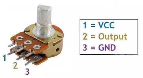
- Connection: Connect the potentiometer terminals 1 and 3 to VCC and GND or vice versa. Terminal 2 (wiper) to the MCU ADC pin.
Note: We can use any of the potentiometers with values between 1kΩ and 10kΩ.
Generating the PWM Signal
- Use the microcontroller to generate a PWM signal with a frequency between 5 kHz and 10 kHz.
- Adjust the PWM duty cycle dynamically based on the ADC reading from the potentiometer.
Verification
- Connect an oscilloscope probe to the PWM output pin of the microcontroller to observe and verify the PWM signal frequency and duty cycle.
So, by considering the above points, we can implement the task.
Below are the solutions to the given task using different microcontrollers
- STM32
- ESP32
- Arduino UNO
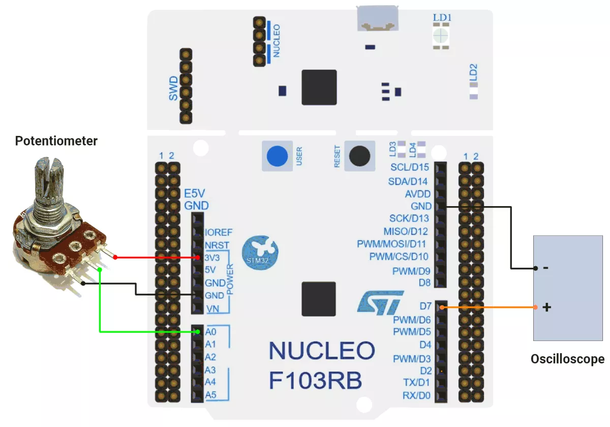
We’re using an STM32 NUCLEO-F103RB board, which runs at a 3.3V logic level.
Key Peripherals Used
- ADC1 Channel 0 (PA0): Reads the analog voltage from the potentiometer.
- TIM1 Channel 1 (PA8): Generates the PWM signal.
- GPIO: PA8 is configured as an alternate function pin for PWM output.
- Optional USART2: Used for serial debugging (configured but not used here).
STM32 Hardware Connection
- Potentiometer Setup:
- Connect the potentiometer’s middle pin (wiper) to PA0 (ADC1_IN0) for analog input.
- Connect the two outer pins of the potentiometer to 3.3V (VCC) and GND to form a voltage divider.
- Use a 10 kΩ potentiometer for best results.
- PWM Setup:
- PWM output pin: PA8 (TIM1 Channel 1).
- Connect the oscilloscope probe to PA8 to observe the PWM signal.
Circuit Diagram
Firmware Implementation
Project Setup in STM32CubeIDE:
- Create a Project
- Open STM32CubeIDE, start a new project, and select the NUCLEO-F103RB board.
- Basic Configuration (via CubeMX inside CubeIDE)
- Clock: HSI oscillator with PLL enabled (configured in
SystemClock_Config). - GPIO:
- GPIO clocks enabled for PORTA, PORTB, PORTC, and PORTD.
- PA0 configured as ADC1 input.
- PWM pin (PA8 – TIM1 CH1) auto-configured via CubeMX.
- ADC1 (Analog Input Source):
- Resolution: 12-bit (0–4095 range).
- Conversion mode: Single, software-triggered.
- Channel: ADC_CHANNEL_0 (PA0).
- Timer 1 (TIM1 – PWM Generator)
- Prescaler = 0 → Timer clock = APB2.
- Period (ARR) = 800-1
- PWM Mode 1 enabled on Channel 1.
- USART2: Enabled at 115200 baud, 8-N-1.
- Clock: HSI oscillator with PLL enabled (configured in
- Code Generation
- CubeMX will automatically generate all the startup code, including:
HAL_Init()– Initializes the HAL library.SystemClock_Config()– Configures HSI + PLL system clock.MX_GPIO_Init()– Configures GPIOs.MX_USART2_UART_Init()– Initializes UART2.MX_ADC1_Init()– Configures ADC1.MX_TIM1_Init()– Configures Timer 1 as a PWM generator.
- This code sets up the hardware and prepares the project for firmware development, so we only need to add our application logic in the user code sections
- CubeMX will automatically generate all the startup code, including:
Code Snippets from main.c
ADC Initialization (MX_ADC1_Init):
hadc1.Instance = ADC1;
hadc1.Init.ScanConvMode = ADC_SCAN_DISABLE;
hadc1.Init.ContinuousConvMode = DISABLE;
hadc1.Init.DataAlign = ADC_DATAALIGN_RIGHT;
This configures ADC1 for single-channel operation with right-aligned 12-bit results.
Timer Initialization (MX_TIM1_Init):
htim1.Init.Period = 800-1;  // ARR register value
htim1.Init.Prescaler = 0;  // No prescaling
sConfigOC.OCMode = TIM_OCMODE_PWM1;  // PWM Mode 1
These functions configure timers for PWM generation.
Macro Definitions:
The provided code defines cleaner code organization:
// ADC value range (12-bit ADC)
#define ADC_MAX_VALUE 4095

// PWM duty cycle range
#define PWM_MAX_VALUE 800
Initialization in main():
Before the while loop, the PWM channel is enabled:
 // Start PWM generation on Timer 1, Channel 1
 // This enables the PWM output on the specified timer channel
 HAL_TIM_PWM_Start(&htim1, TIM_CHANNEL_1);
Main while Loop:
while (1) {
  // Start ADC conversion
  HAL_ADC_Start(&hadc1);

  // Wait for ADC conversion to complete with a timeout of 20ms
  HAL_ADC_PollForConversion(&hadc1, 20);

  // Read the converted ADC value (0-4095 for 12-bit ADC)
  uint16_t adcValue = HAL_ADC_GetValue(&hadc1);

  uint16_t pwmVlaue = (PWM_MAX_VALUE * adcValue) / ADC_MAX_VALUE;

  // Update PWM duty cycle based on ADC reading
  // This creates a direct relationship between the analog input and the PWM output
  __HAL_TIM_SET_COMPARE(&htim1, TIM_CHANNEL_1, pwmVlaue);

  // Small delay to stabilize the system and prevent overwhelming the ADC
  HAL_Delay(1);
}- Reads an analog input (ADC value, 0–4095).
- Scales it to a PWM range (e.g., 0–799).
- Updates a PWM signal (e.g., to control LED brightness or motor speed).
- Repeats with a small delay (1ms) to stabilize readings.
PWM Frequency Calculation
- System Clock = 8 MHz (HSI / 2 with PLL multiplier).
- Timer Clock = 8 MHz (APB2 prescaler = 1).
- Prescaler = 0 (no division).
- ARR (Auto-Reload Register) = 799.
PWM frequency is calculated as:
PWM frequency = Timer Clock / (ARR + 1) = 8 MHz / 800 = 10 kHz.
Maintaining a constant PWM frequency while adjusting duty cycle ensures motor speed control is smooth and consistent.
Download Project
The complete STM32CubeIDE project (including .ioc configuration, main.c, and HAL files) is available here:
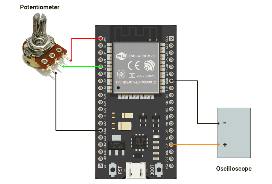
We are using the ESP32 DevKit v4 development board and programming it using the Arduino IDE.
- Before uploading, make sure to select “ESP32 Dev Module” as the board to ensure correct settings and compatibility.
The ESP32’s MCPWM unit is a dedicated motor-control peripheral, providing high-resolution PWM, flexible frequency, dead-time insertion, and complementary outputs, unlike LEDC, which is optimized for LEDs.
Pins to Avoid for PWM on ESP32
- GPIO6–11 → Used for flash memory
- GPIO34–39 → Input pins only (not suitable for PWM output)
- GPIO0, GPIO2, GPIO15 → Strapping pins (affect boot mode)
- EN, SENSOR_VP, SENSOR_VN → Reserved for special functions
ESP32 Circuit Connection
- Connect the DSO to the GPIO pin 14.
- Connect the potentiometer to the GPIO pin 34.
Circuit Diagram
ESP32 Firmware Implementation
Code
#include "driver/mcpwm.h"

#define MOTOR_PIN 14  // PWM output to motor driver input
#define POT_PIN 34    // Potentiometer input (ADC1, GPIO34 is input-only)

void setup() {
  Serial.begin(115200);

  //Configure PWM on GPIO2
  mcpwm_gpio_init(MCPWM_UNIT_0, MCPWM0A, MOTOR_PIN);

  //Initialize PWM configuration
  mcpwm_config_t pwm_config;
  pwm_config.frequency = 10000;                // 10 kHz PWM (quiet, safe for motor)
  pwm_config.cmpr_a = 0;                       // Initial duty cycle = 0%
  pwm_config.cmpr_b = 0;                       // Not used
  pwm_config.duty_mode = MCPWM_DUTY_MODE_0;    // Active high
  pwm_config.counter_mode = MCPWM_UP_COUNTER;  // Count-up mode

  mcpwm_init(MCPWM_UNIT_0, MCPWM_TIMER_0, &pwm_config);

  //Configure ADC
  analogReadResolution(12);  // 12-bit ADC (0–4095)
}

void loop() {
  // Read potentiometer (0–4095)
  int potValue = analogRead(POT_PIN);

  // Convert to duty cycle (0–100%)
  float dutyCycle = ((float)potValue / 4095.0) * 100.0;

  // Update motor speed (apply duty cycle)
  mcpwm_set_duty(MCPWM_UNIT_0, MCPWM_TIMER_0, MCPWM_OPR_A, dutyCycle);
  mcpwm_set_duty_type(MCPWM_UNIT_0, MCPWM_TIMER_0, MCPWM_OPR_A, MCPWM_DUTY_MODE_0);

  // Debugging
  // Serial.printf("Pot: %d   Duty: %.2f%%\n", potValue, dutyCycle);

  delay(10);  // Small delay for stable serial output
}
Code Explanation
PWM Setup
MOTOR_PIN (GPIO14)is configured as MCPWM output (MCPWM0A) to drive the motor.- PWM frequency = 10 kHz, initial duty cycle = 0%.
- MCPWM operates in up-count mode, active-high.
ADC Setup
POT_PIN (GPIO34)reads a potentiometer.- ADC resolution = 12-bit → values 0–4095.
Loop Operation
- Read potentiometer value →
potValue. - Map ADC value (0–4095) to PWM duty cycle (0–100%).
- Update MCPWM duty cycle with
mcpwm_set_duty()→ motor speed changes accordingly. mcpwm_set_duty_type()ensures duty cycle mode is active-high.- Optional serial debug prints (commented out).
- Small delay for stability.
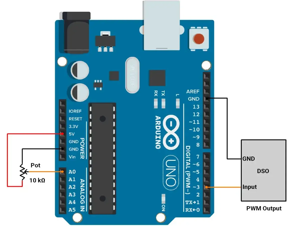
We are using the Arduino UNO development board and programming it using the Arduino IDE.
- Before uploading, make sure to select “Arduino UNO” as the board to ensure correct settings and compatibility.
First of all, let's do the hardware connection,
- We need to connect the potentiometer to the Arduino's ADC.
- We can use any of the available PWM channels, and for this implementation, we will use PWM pin 3.
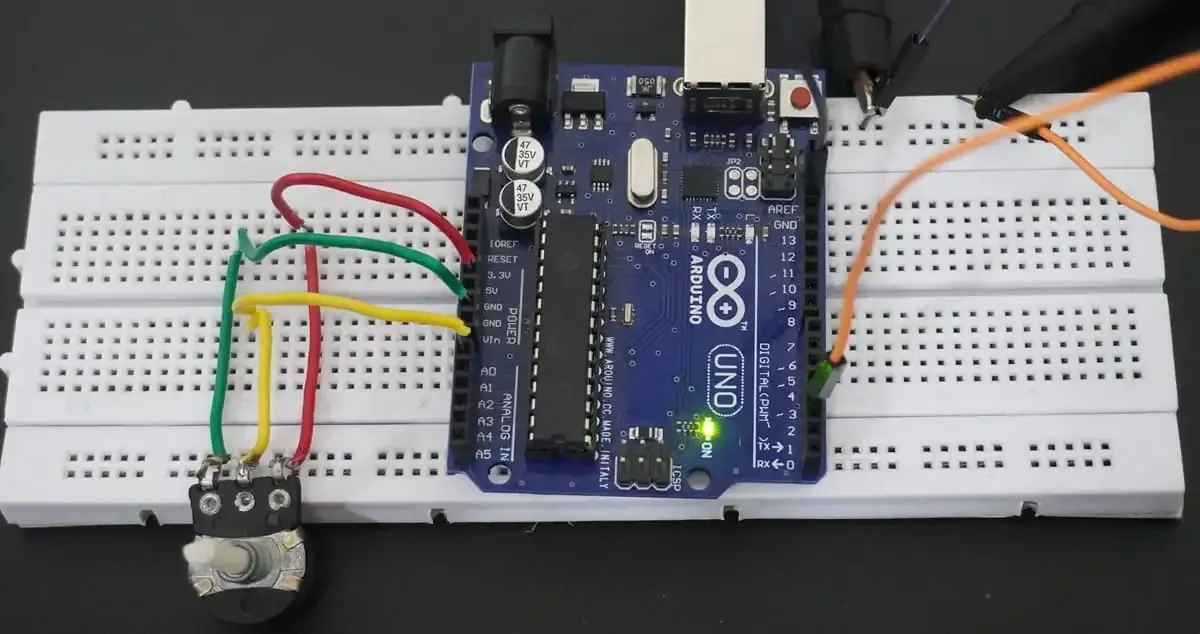
Arduino UNO Circuit connection
Arduino UNO Firmware Implementation
To control the duty cycle of PWM:
- ADC values range from 0 to 1023, and PWM values range from 0 to 255
- ADC and PWM values are mapped using the
map()function. - Change the duty cycle of PWM using the OCR2B register.
Default PWM Frequency:
- On the Arduino Uno, PWM pin 3 is controlled by Timer2.
- The default PWM frequency for pin 3 is 490 Hz (when using
analogWrite()).
How to Change PWM Frequency on Arduino UNO:
To generate a PWM signal between 5 kHz and 10 kHz on Pin 3 using Timer2,
Formula:
PWM Frequency = Clock Frequency / ( Prescaler * 256 )
Where Clock Frequency = 16 MHz (Arduino clock speed).
Prescaler Calculation:
Prescaler = Clock Frequency / ( PWM Frequency * 256 )
- For 5 kHz: Prescaler ≈ 12.5
- For 10 kHz: Prescaler ≈ 6.25
- Closest Prescaler: 8
Resulting Frequency:
With prescaler = 8.
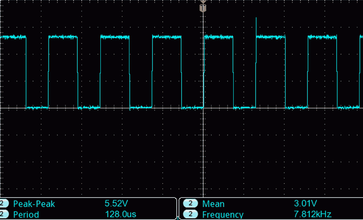
PWM Frequency = 16000000/ ( 8 * 256) = ~ 7.8 kHz
Timer2 Configuration:
- Set Fast PWM Mode: WGM20=1, WGM21=1.
- Set Non-Inverted Output: COM2B1=1.
- Set Prescaler to 8.
TCCR2A = (1 << WGM20) | (1 << WGM21) | (1 << COM2B1); // Fast PWM, non-inverted
TCCR2B = (TCCR2B & 0b11111000) | 0x02; // Prescaler = 8
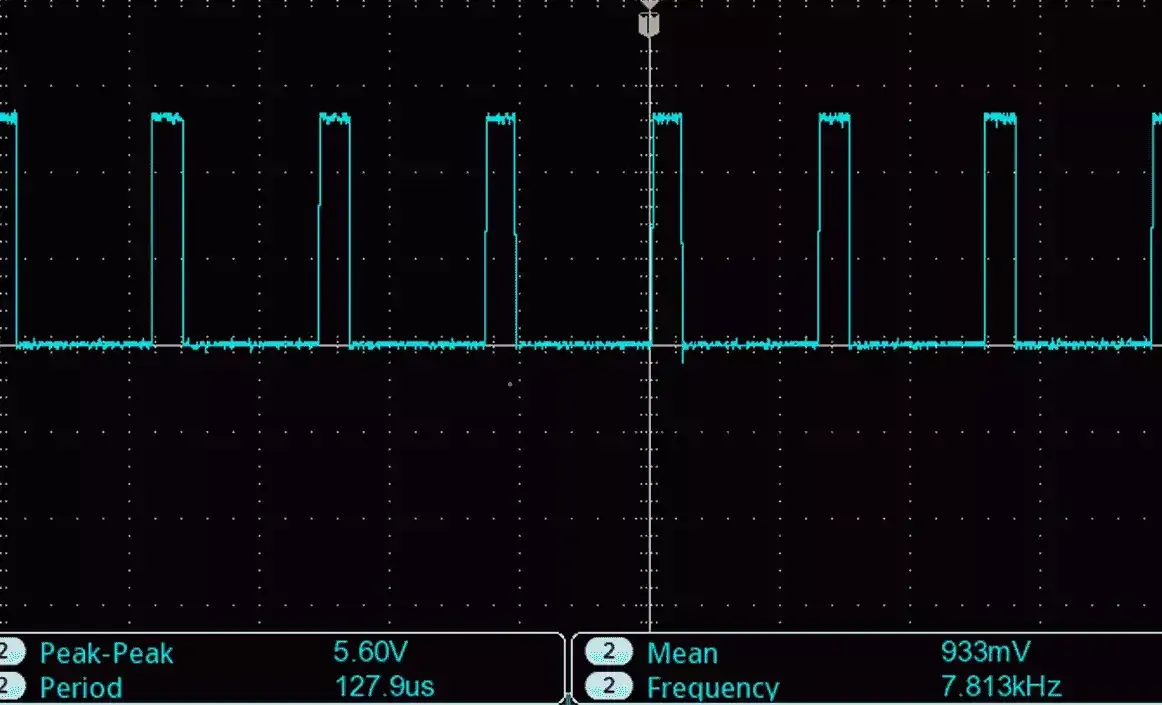
Final PWM Frequency:
Achieved frequency = 7.8 kHz, within the desired range.
Code
#define pwmPin 3   // PWM output on Pin 3
#define potPin A0  // Potentiometer connected to Analog Pin A0

/*
  Setup function: Configures PWM on Pin 3 using Timer2
*/
void setup() {
  pinMode(pwmPin, OUTPUT);  // Set Pin 3 as output

  /*
    Configure Timer2 for Fast PWM mode with a frequency of ~7.8 kHz
    - Fast PWM: WGM20 and WGM21 set
    - Non-inverted PWM: COM2B1 set
    - Prescaler: 8 (TCCR2B = 0x02)
  */
  TCCR2A = (1 << WGM20) | (1 << WGM21) | (1 << COM2B1);
  TCCR2B = (TCCR2B & 0b11111000) | 0x02;
}

/*
  Main loop: Reads potentiometer and adjusts PWM duty cycle
*/
void loop() {
  // Read analog value (0-1023) from potentiometer
  int potValue = analogRead(potPin);

  // Map analog value to PWM duty cycle (0-255)
  int pwmValue = map(potValue, 0, 1023, 0, 255);

  // Set PWM duty cycle for Pin 3
  OCR2B = pwmValue;

  // Add a small delay to stabilize readings
  delay(10);
}
Output
PWM with 20% Duty Cycle :
PWM with 70% Duty Cycle :