SPI Quick Reference Guide
SPI Basics
SPI(Serial Peripheral Interface) is a High-Speed, synchronous, full-duplex, serial Communication protocol.
- Short distance protocol: distance <10cm.
- High Speed: Faster than I2C and UART ( 1MHz - 200MHz range - depends on controller clock- default 4MHz in Arduino UNO).
SPI communication is commonly used to interface such as Memory devices (SD cards, EEPROM, Flash), displays(OLED), sensors, and ADC/DAC.
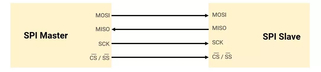
SPI Pins (4-pin)
| Signal | Full Name | Direction | Description |
|---|---|---|---|
| SCK | Serial Clock | Master → Slave | Generated by the master to synchronise data transfer |
| MOSI | Master Out Slave In | Master → Slave | Data from master to slave |
| MISO | Master In Slave Out | Slave → Master | Data from slave to master |
| SS/CS | Slave Select / Chip Select | Master → Slave | Selects which slave is active (Active-Low) |
No Addressing for Slave- SPI uses chip select (SS) lines to select slaves.
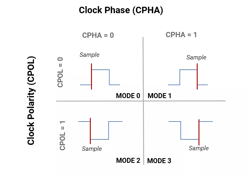
SPI Modes
SPI has 4 modes, determined by CPOL (Clock Polarity) and CPHA (Clock Phase).
- Clock Polarity (CPOL) – Defines the idle state of the clock. (LOW or HIGH)
- Clock Phase (CPHA) – Determines when data is sampled (read) (On the RISING edge or the FALLING edge).
| Mode | CPOL | CPHA | Clock Idle State | Data Sampled On |
|---|---|---|---|---|
| 0 | 0 | 0 | Low | Rising Edge |
| 1 | 0 | 1 | Low | Falling Edge |
| 2 | 1 | 0 | High | Falling Edge |
| 3 | 1 | 1 | High | Rising Edge |
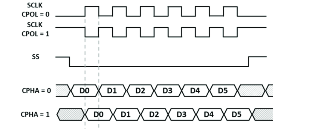
SPI Mode Diagram
Example
Mode 0- In SPI Mode 0 (CPOL=0, CPHA=0), clock polarity is low when idle; data is sampled on the rising edge as shown in the given diagram.
Data sampling w.r.t clock polarity and phase.
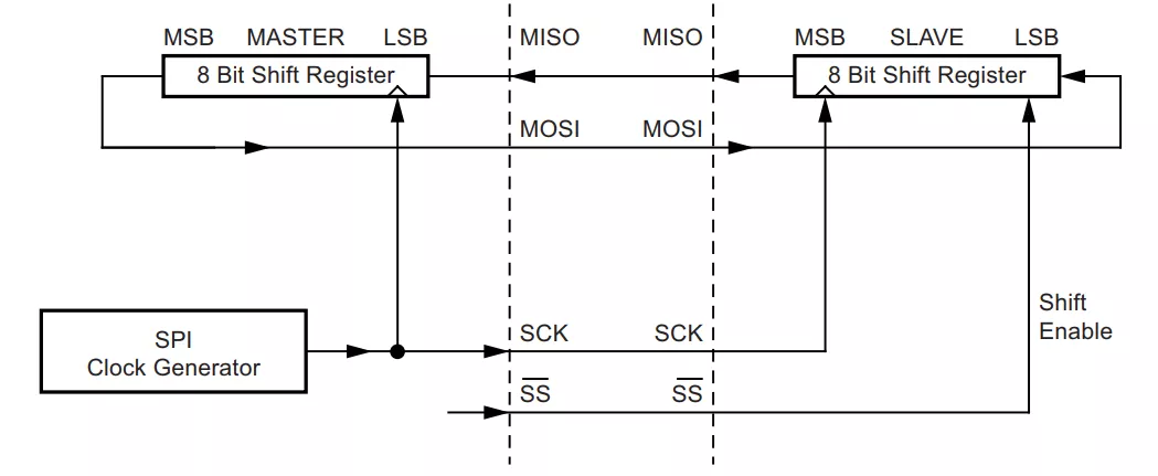
SPI Data Transfer
- Master pulls SS/CS LOW to start communication with a particular slave.
- It is a full-duplex communication protocol, so both master and slave send and receive data bit by bit serially at the same time in synchronization with clock.
- If the master only wants to read from the slave, it must send dummy data to the slave's response.
- Data transfer in SPI is both directional ( MSB to LSB or LSB to MSB).
Daisy-Chaining Method (Multi-Slave Configuration)
- This method connects all SPI slaves in series, shifting data continuously through all devices during SCK pulses.
- Each slave latches its assigned data portion either on the CS edge (most common) or after a fixed bit count, enabling simultaneous data propagation and per-slave capture.
- A single shared SCK and SS line minimizes hardware complexity.
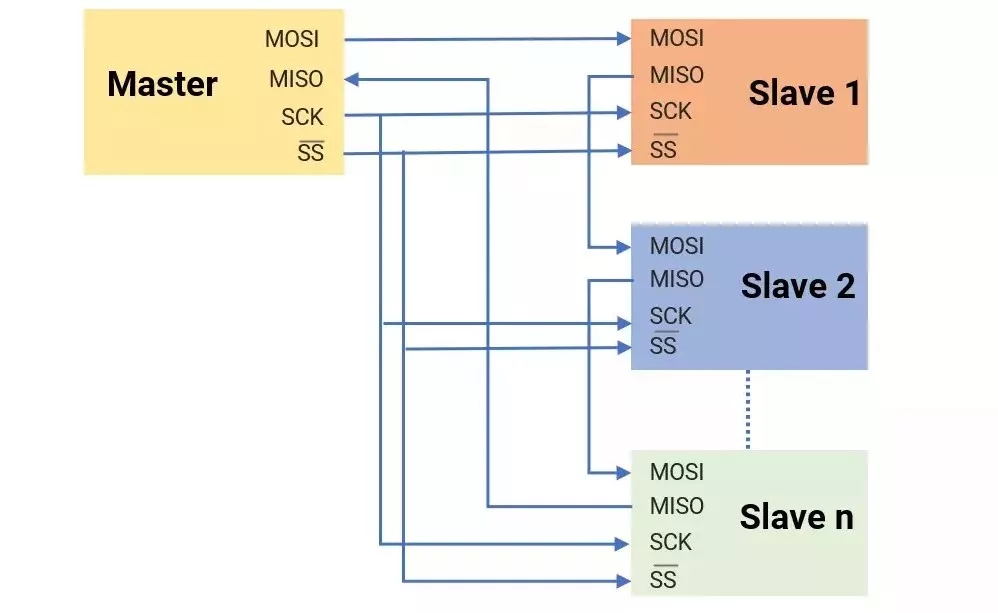
Note: This protocol is not designed for a multi-master configuration by default.
SPI in Micro-Controllers
SPI is an on-board protocol found in most controllers ( AVR, PIC, ARM, and RISC).
Generally following registers are present in controllers. (with reference to AVR ATmega 328P)
| Registers | Description |
|---|---|
| SPCR | SPI Control Register: enabling SPI and interrupt, selecting Master/Slave mode, clock polarity (CPOL), phase (CPHA), and data order (MSB/LSB first) |
| SPISR | SPI Status Register: flags(SPIF, WCOL) help manage and monitor SPI communication and double the Speed in SPI. |
| SPDR | SPI Data Register - writing/ reading data buffer for SPI communication |
Writing SPI Driver (Master- Writing Data)
- Set SPI pins: Configure MOSI, SCK, and SS as outputs; MISO as input.
- Enable SPI: Configure the SPI control register to enable SPI and select master mode.
- Set clock: Configure clock polarity, phase, and speed in the SPI control register.
- Send data: Write to the SPI buffer to start transmission. Read data: Read received data from the SPI buffer.
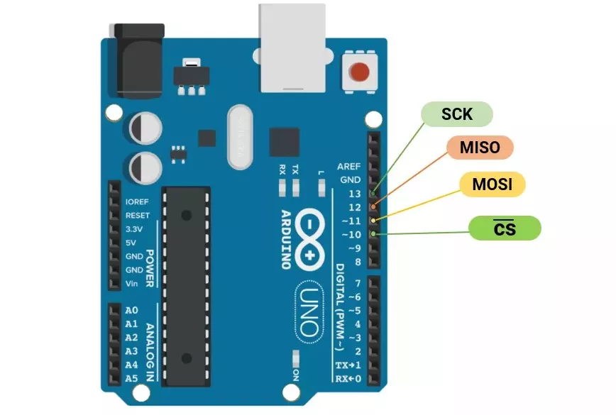
SPI in Arduino UNO
SPI communication pins in Arduino UNO
Arduino SPI.h Library Functions
| Functions | Descriptions |
|---|---|
SPI. begin() | Initializes the SPI bus by setting SCK, MOSI, and SS to outputs |
SPI. beginTransaction(mySettings) | Initializes the SPI bus. Note that calling SPI.begin() is required before calling this one. |
mySetting(speedMaximum, dataOrder, dataMode) | SPISettings object is used with SPI.beginTransaction() for configuration. |
SPI. endTransaction() | Stop using the SPI bus. |
SPI. end() | Disables the SPI bus (leaving pin modes unchanged). |
SPI. setBitOrder(order) | Sets the order of the bits shifted out. |
SPI. setClockDivider(divider) | Sets the SPI clock divider relative to the system clock. |
SPI. setDataMode(mode) | Sets the SPI data mode. |
SPI. transfer() | Transfer and receipt of the data. |
SPI. usingInterrupt() | Inform the SPI library to avoid conflicts with a specific interrupt. |
Example
Master sends 0x80 to the slave using SPI.
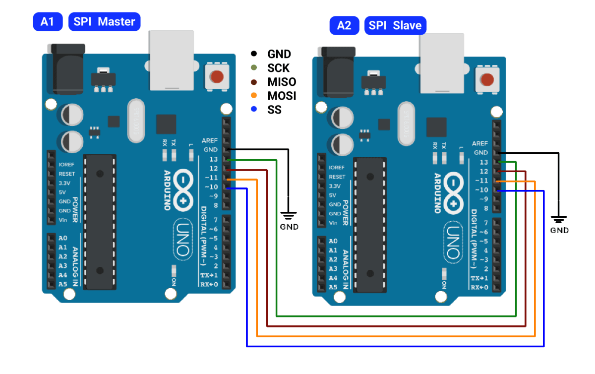
Master Code(A1)
#include <SPI.h>

void setup() {
  SPI.begin();             // Initialize SPI bus
  pinMode(SS, OUTPUT);     // Set SS pin as output
  digitalWrite(SS, HIGH);  // Deselect slave initially
  Serial.begin(9600);      // For debug (optional)
}

void loop() {
  digitalWrite(SS, LOW);               // Select slave
  byte received = SPI.transfer(0x80);  // Send 0x80 and read response
  digitalWrite(SS, HIGH);              // Deselect slave

  Serial.print("Sent: 0x80 | Received: 0x");
  Serial.println(received, HEX);  // Print slave's response

  delay(1000);  // Wait 1 second
}
Slave Code(A2)
#include <SPI.h>

volatile byte receivedData;

void setup() {
  Serial.begin(9600);
  pinMode(MISO, OUTPUT);    // Set MISO as output (Slave)
  SPCR |= (1 << SPE);       // Enable SPI (Slave mode)
  SPCR |= (1 << SPIE);      // Enable SPI Interrupt
}

ISR(SPI_STC_vect) {        // SPI Interrupt Service Routine
  receivedData = SPDR;      // Store received byte
  Serial.print("Received: 0x");
  if (receivedData < 0x10)
    Serial.print("0"); // Pad single digit hex
  Serial.println(receivedData, HEX); // Print in HEX
}

void loop() {
  // Do nothing (SPI runs via interrupt)
}
Concept understood? Let's apply and learn for real