ADC Quick Reference Guide
What is ADC?
An ADC converts analog signals (temperature, voltage) into a digital value.
ADC is used for reading voltage output from temperature sensors (e.g., LM35), light sensors (e.g., LDR), and to read potentiometers, etc.
ADC resolution
How many digital values (steps) can an ADC use to represent an input analog signal.
Higher resolution gives more precise readings.
- 0 to 5V (analog input) → 0 to 1024 (1024 digital values used)
Here, 0 to 5V is represented in 1024 steps (for 10-bit ADC, AVref = 5V).
ADC Steps = 2 ^ n
where, n = number of ADC bits
- The higher the steps = the ADC can detect smaller changes in the input signal
Resulting in a more accurate digital representation.
E.g. 4-bit ADC with a 5V AVref can detect a voltage change of 312.5 mV.
But a 10-bit ADC can detect a voltage change of 4.88 mV .(more precise) - Formula :
Minimum voltage change ADC can detect = AVref / number-of-steps.
= 5 / 1024
= 4.882 mV
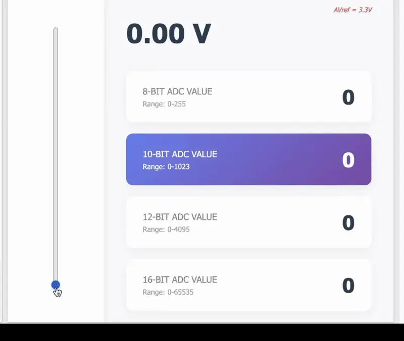
The GIF below shows how different resolutions of ADC (8-bit, 10-bit- 12-bit, and 16-bit) vary the digital OUTPUT for input analog voltage change.
AVref = 5V
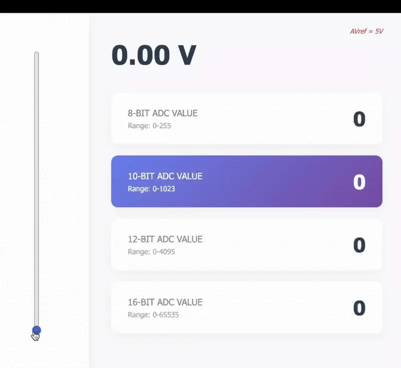
AVref = 3.3V
ADC Sampling rate
The number of times the ADC measures (samples) the analog signal per second.
- measured in samples per second (SPS) or Hz (Hertz).
- Sampling period is the time taken by the controller to capture and convert a single ADC value.
- Sampling rate (Hz) = 1 / sampling period (seconds)
Arduino UNO can achieve a maximum sampling rate of 15 kHz.
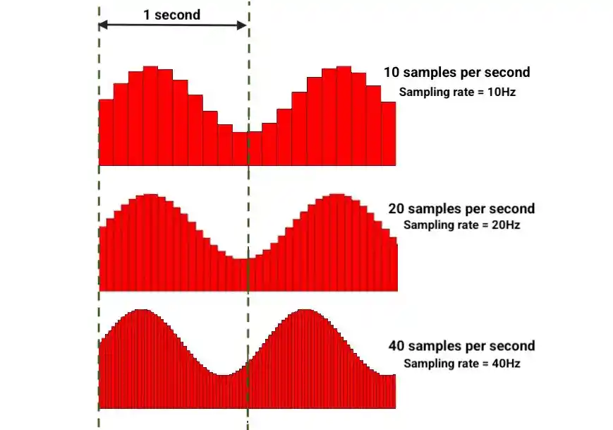
Higher sampling rate results in a more accurate digital representation of the input signal.
ADC Registers
Generally, in controllers (AVR, PIC) following types of ADC registers are present.
Considering AVR controllers:
| Register | Description |
|---|---|
| ADMUX | Selects the reference voltage and the ADC input channel (A0 to A7) |
| ADCSRA | Controls the ADC, enabling it, starting conversions, and setting the prescaler. |
| ADCL & ADCH | Holds the bits of the ADC result. |
NOTE: ARM and RISC-based 32-bit controllers have more add-on registers (e.g., conversion control registers, sampling time registers, interrupt control registers, etc).
Driver setup (AVR)
Most microcontrollers have a single ADC unit shared across multiple input channels. Multiplexers allow one channel to be read at a time.
- ADC Configuration
- Set the reference voltage for ADC (AVref).
- Choose the resolution (e.g., 8-bit or 10-bit).
- Select the input channel. (GPIO pin)
- Configure the ADC clock using a prescaler to ensure proper sampling speed.
- (For interrupt-based operation)
- Enable the ADC interrupt.
- Write an interrupt service routine (ISR) to handle ADC completion.
- Enable global interrupts.
- ADC Conversion Using Polling
- Start the ADC conversion.
- Wait until the conversion is complete (by checking the appropriate status flag).
- Read the digital result from the ADC result register.
- ADC Conversion Using Interrupts
- Start the ADC conversion.
- When conversion completes, the ISR is automatically triggered.
- Inside the ISR, read the ADC result.
Arduino Functions
Function | Description |
|---|---|
analogRead(pin) | Reads the analog value from a specified pin (returns a value between 0 and 1023 for 10-bit ADC). |
analogReference(type) | Sets the reference voltage for the ADC. Options include DEFAULT, INTERNAL, EXTERNAL, etc. |
Examples
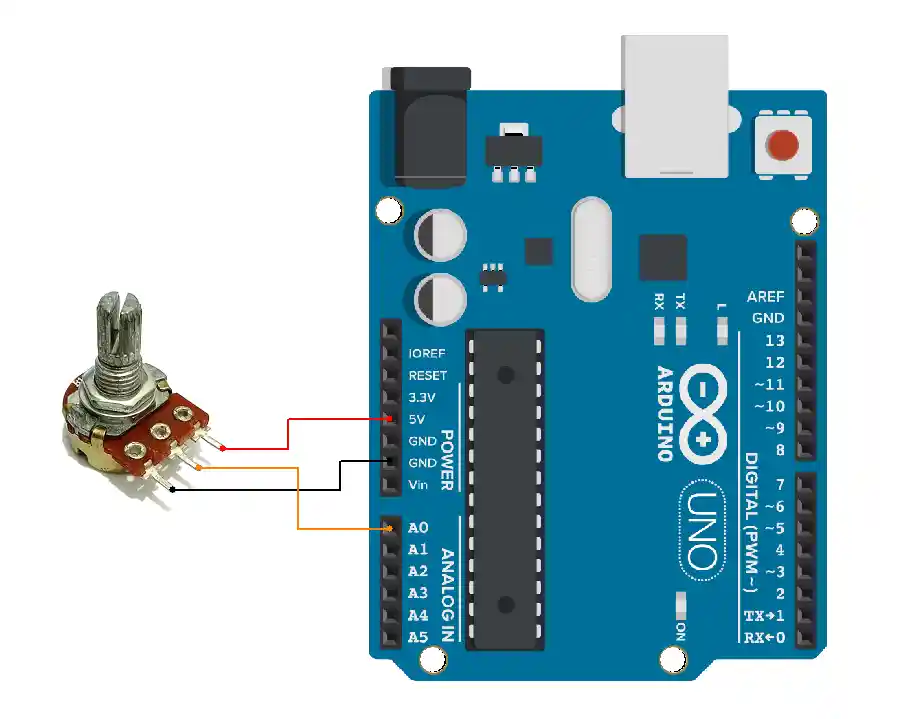
1. Potentiometer ADC Reading

void setup() {
  Serial.begin(115200);
}
void loop() {
  int val = analogRead(A0);
  Serial.println(val); // prints 0 to 1023
  delay(100);
}
2. Potentiometer Voltage Reading

void setup() {
  Serial.begin(115200);
}

void loop() {
  int val = analogRead(A0);
  float voltage = sensorValue * (5.0 / 1023.0); // convert to voltage
  Serial.println(voltage); // prints 0 to 5.0
  delay(100);
}
3. Change ADC reference voltage
void setup() {
  Serial.begin(115200);

  // Set ADC reference to internal = 1.1V
  analogReference(INTERNAL);
}

void loop() {
  int val = analogRead(A0);
  float voltage = sensorValue * (1.1 / 1023.0);
  Serial.println(voltage); // prints 0.0 to 1.1
  delay(100);
}Concept understood? Let's apply and learn for real