Timer Quick Reference Guide
Timer Basic
- A timer is a hardware peripheral in a microcontroller that increments a timer's counter register based on a clock source.
- It helps in time measurement, periodic event generation, precise delays, and waveform generation, etc.
- Generally, there are multiple timers available in a single controller, i.e., Timer-1, Timer-2, Timer-3, etc. They are either 8-bit, 16-bit, or 32-bit.
- 8-bit Timer →2^8 is 256, so it counts from 0–255
- 16-bit Timer →2^16 is 65536, so it counts from 0–65535
- Some high-end MCUs have 32-bit or 64-bit timers
- Timer Clock
- Clock Source
Timers can run on system clock (e.g., 16 MHz on ATmega328P), prescaled clock (divide system clock by 8, 64, 256, etc.), and an external clock. - Prescaler
A Prescaler is a hardware divider that reduces the system clock frequency before it reaches the timer.
For example, with a 16 MHz system frequency and a prescaler of 2, the timer input frequency will be 8 MHz (16 MHz / 2 = 8 MHz).
- Clock Source
- Timer Frequency = CPU Clock frequency / Prescaler.
Common Timer Modes and Functionalities
| Modes | Description | Uses |
|---|---|---|
| Timer Mode | Increments to the timer register are based on a clock source. | Precise Delay generation, Periodic Event Triggering. |
| Counter Mode | Counts external pulses (events). | Pulse counting, RPM sensing |
| Input Capture Mode | Records the timervalue when an external event occurs. | Pulse width measurement |
| Compare Mode | Generates an interrupt or toggles a pin or reset timer when the timer matches a set value. | PWM, waveform generation, and precise delay generation. |
| CTC Mode | Reset the timer on the compare match. | waveform generation and precise delay generation. |
| PWM Mode | Generates PWM signals. | Motor speed control, LED dimming. |
| One-Pulse Mode | Generates a single pulse when triggered. | Precise one-shot pulse (e.g., for triggering external devices). |
Note: Not all microcontrollers support all the Timer modes listed above. Some microcontrollers may offer similar functionalities under different names or configurations.
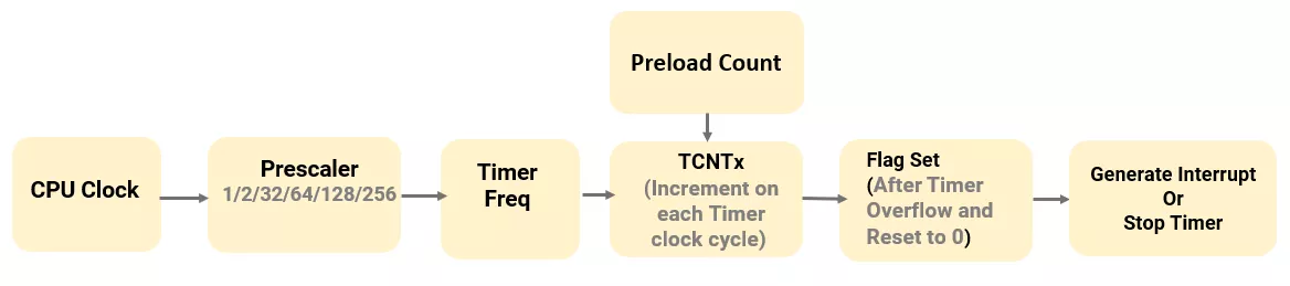
1. Timer Mode
In this mode, the Timer counter counts up with each clock pulse. When it reaches its max value (like 255 for 8-bit), it overflows and resets to 0.
After reset, it sets an overflow flag and triggers an interrupt if enabled.
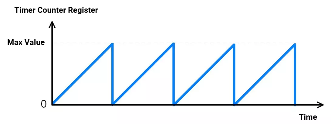
Setting a custom initial value in the Timer Counter register allows us to create precise delays. For example, loading the timer with 100 means it will overflow after 155 ticks (from 100 to 255).
2. Counter Mode
Counter Mode is like Timer Mode, but it uses external pulses instead of the internal clock. It's ideal for counting events like signal edges, button presses, or sensor pulses.
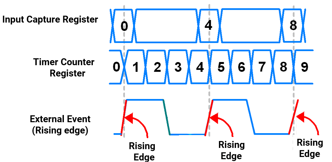
3. Input Capture Mode
Capture Mode copies the current timer counter register value into the Input Capture Register whenever a defined external event (e.g., rising edge) occurs on a specific input pin.
This allows measure the precise timing of external signals by saving the timer value exactly when the event happens.
For example, given below, the Input is captured at the rising edge (external event).
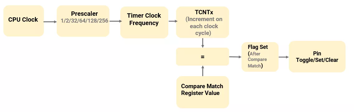
4. Compare Mode
In this mode, the timer counts up with each clock pulse.
When the counter matches the compare register value, it triggers an action (e.g., toggle, set, clear output pin) or generates an interrupt (if enabled).
Used in PWM, waveform generation, and precise delays.
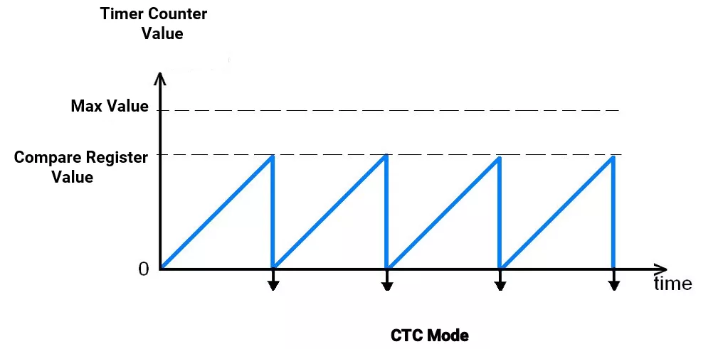
5. CTC (Clear Timer Compare Match) Mode
CTC Mode resets the timer to zero when it matches a value in the Output Compare Register.
This allows precise control over timing intervals without overflowing the counter. It's commonly used for generating accurate delays, waveforms, or periodic interrupts.
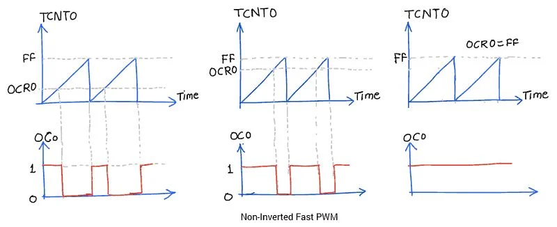
6. PWM Mode
PWM Mode uses the timer to generate PWM signals with a variable duty cycle by comparing the Timer/counter register value with the Output Compare Register value.
It is useful for tasks like motor control, LED dimming, and analog signal simulation.
There are 2 configurations in the Timer’s PWM mode :
- Fast PWM
- Phase Correct PWM
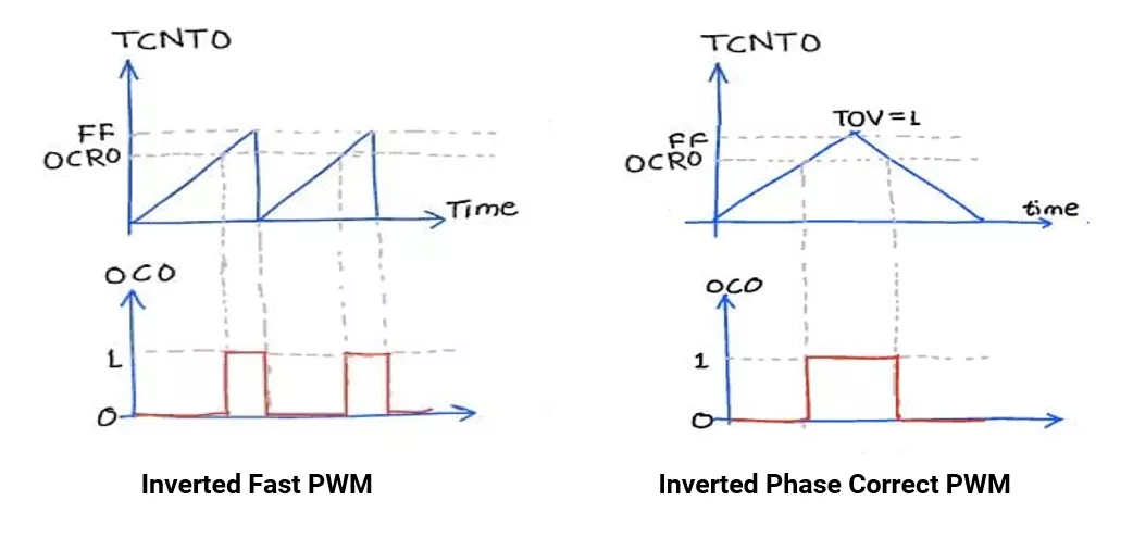
Inverted Fast PWM and Phase Correct PWM (w.r.t. Atmega328p)
Fast PWM Mode: In this, the timer counts from BOTTOM (0) to TOP, then resets to 0, repeating continuously.
This produces a high-frequency PWM signal. The duty cycle is controlled by the compare register (OCRx). Since it updates at the top, it's faster but less precise for timing-critical tasks. Ideal for applications like motor speed control or LED dimming.
Phase Correct PWM Mode: In this, the timer counts up from BOTTOM to TOP, then back TOP to BOTTOM (dual-slope). This creates a symmetric PWM waveform centered around the TOP value, giving less frequency but better phase accuracy. It is useful when timing symmetry is critical, like in power electronics.
7. One-Pulse Mode:
One Pulse Mode allows the timer to generate a single, timed pulse when triggered. The timer starts on an input event, counts for a set duration, then stops—ideal for one-shot signal generation or event response.
Timers in Microcontroller
The timer is an important peripheral present in every microcontroller, like AVR, STM, 8051, etc.
Understanding of the Timer concerning ATmega328P.
ATmega328P has 3 timers Timer0(8-bit),Timer1(16-bit) and Timer2(8-bit) with Normal, CTC(Clear Timer on Compare), Capture and PWM(Fast/ Phase Correct) mode.
Generally, the following registers are present in controllers. (considering AVR ATmega 328P)
| Register | Description |
| TCCRnA/B | Timer Control register - Set the timer mode, prescaler, and PWM behavior. |
| TCNTn | Timer Counter - holds the current count value of the Timer |
| OCRnA/B | Timer Compare Match Register - Hold value to be compared |
| TIMSKn | Interrupt Mask Register- Enable or disable basic timer interrupt. |
| TIFRn | Interrupt Flag Register - shows which timer interrupt flags are set |
| ICRn | Input Capture Register(Timer 1 only) - capture timer value on edge. |
Timer-related functions in Arduino UNO
In Arduino, for various cases, we need to configure registers, since built-in functions are limited.
Available standard Arduino functions:
| Functions | Timer Used | Description |
delay(ms) | Timer0 | The controller waits (stuck) for the given delay in milliseconds. |
millis() / mircos() | Timer0 | Returns the number of milliseconds/microseconds since the Arduino started running. |
analogWrite(pin, value) | Timer0/1/2 | Generate a PWM signal on the following digital pins
|
tone(pin, frequency, duration) | Timer2 | Generate a square wave |
noTone(pin) | Timer2 | Stops the generation of a square wave triggered by a tone() |
pulseIn(pin, value, timeout) | Timer0 | Measure pulse width on the specified pin. |
Examples
1. This code toggles the LED after every 16 milliseconds using timer2 (8-bit) in normal(Timer) mode with a 16MHz clock frequency and a 1024 prescaler.
Explanation:
In the below example, we want to generate a 16 ms delay.
The Timer is configured in Normal (Timer) Mode. In this mode, the timer counts up from the preloaded value in the Timer Counter register to its maximum value(255 for an 8-bit timer), then overflows.
The timer2 is an 8-bit timer with 16 MHz and a 1024 prescaler, then
- Timer Frequency = 16MHz / 1024 = 15.652 kHz
- Time per tick = 1/ Timer Frequency = 1 / 15.652 kHz = 64 µs → The Timer counter register is incremented after every 64 µs.
- Ticks needed = 16000 µs / 64 µs = 250
- Preload Count = 256 − 250 = 6
Load the timer counter register with 6 → Timer overflows after 250 ticks, and it generates a 16 ms delay.
Code
void setup() {
  pinMode(7, OUTPUT);

  // Timer2 configuration for ~16ms delay
  TCCR2A = 0;  // Normal mode (WGM20, WGM21 = 0)
  TCCR2B = 0;
  TCNT2 = 6;   // Load initial value for 16ms delay

  // Prescaler 1024, start timer
  TCCR2B = (1 << CS22) | (1 << CS21) | (1 << CS20);
}

void loop() {
  TCNT2 = 6;  // Reload timer for the next cycle
  PORTD ^= (1 << PORTD7);  // Toggle PORTD7 (digital pin 7)

  // Wait for Timer2 overflow (~16ms)
  while ((TIFR2 & (1 << TOV2)) == 0);
  TIFR2 |= (1 << TOV2);  // Clear overflow flag by writing 1
}
2. Generation of a 40% duty cycle non-inverting PWM signal using Timer0 with a 16MHz CPU clock and a 64 prescaler.
Explanation:
In the following code, Timer0 is configured in Fast PWM mode (non-inverting).
Generating Non-Inverting PWM on Pin 6 (Arduino UNO) using Fast PWM (Timer0):
- OCR0A Value: 102 (≈40% of 255)
- Duty Cycle: 40%
Here timer is configured in Fast PWM mode, with Non-Inverting mode.
Means, when the value in register OCR0 matches the timer value, the output on pin 6 toggles (LOW) & on Timer overflow, the output of pin 6 toggles again (HIGH).
Thus, by varying the value of the OCR0A register, we can vary the duty cycle of the PWM.
In this example, OCR0A Value: 102which is around 40% of 255. Thus, the generated PWM has a duty cycle of 40%.
Code
void setup() {
  noInterrupts();  // disable the interrupts
  pinMode(6, OUTPUT);  // OC0A output (Pin 6)

  TCCR0A = (1 << WGM01) | (1 << WGM00);  // Fast PWM mode
  TCCR0A |= (1 << COM0A1);               // Non-inverting mode on OC0A
  TCCR0B = (1 << CS01) | (1 << CS00);    // Prescaler = 64

  OCR0A = (255 * 0.4);  // 40% duty cycle → 102
}

void loop() {
  // PWM runs automatically in hardware
}
Note: Timer0 is used by Arduino's millis(), micros(), and delay() functions, which rely on Timer0 interrupts. For accurate timing with Timer0, disable these interrupts to avoid interference.
3. Generation of a 250Hz square wave on pin 9 (OC1A pin) using CTC mode without prescaler. The CPU clock is 16 MHz.
Explanation:
In the below example, we want to generate a 250Hz square wave.
Timer 1 is configured in CTC Mode. In this mode, the timer counts up from the initial value 0 to its Compare match register value, when a compare match occurs, on next timer clock timer reset to 0.
To generate a square, we toggled pin 9 on a compare match.
Timer 1 is a 16-bit timer with 16 MHz and a 1 prescaler, then
- Timer Frequency = 16MHz / 1 = 16 MHz
- Time per tick = 1/ Timer Frequency = 1 / 16MHz = 62.5 nanoseconds→ The Timer counter register is incremented after every 62.5 nanoseconds.
- To generate a 250 Hz square wave, toggle pin 9 every 2 ms since each cycle is of 4 ms (2 ms high, 2 ms low).
Time Period of Square wave = 1 / 250 Hz = 4 ms. - Ticks needed = 2 milliseconds / 62.5 nanoseconds = 32000
- Preload Count = 32000 -1 = 31999
Load the compare match register with 31999 →The timer counts from 0, and upon reaching the compare register value 31999, it resets to 0 and toggles the pin.
Code:
void setup() {
  TCCR1A = (1 << COM1A0);   // Toggle OC1A on compare match
  TCCR1B = (1 << WGM12) | (1 << CS10); // CTC mode, prescaler = 1
  OCR1A = 31999;            // Set compare value
  DDRB |=  (1 << PB1);     // D9 (PB1) as outputs

}
void loop() {
}
4. Square wave signal frequency calculation using capture mode of Timer1 in Arduino UNO.
Note: CPU clock frequency is 16MHz and has no prescaler used.
Explanation:
In the example below, we want to calculate the frequency of the square wave.
In Input Capture Mode, Timer 1 runs continuously. When an external signal rising/falling edge occurs at a specific pin, the current timer counter register value is instantly copied into the input capture register.
Timer 1 is a 16-bit timer with a 16 MHz clock frequency and a 1 prescaler, then
- Timer Frequency = 16MHz / 1 = 16 MHz
- Time per tick = 1/ Timer Frequency = 1 / 16MHz = 62.5 nanoseconds→ The Timer counter register is incremented after every 62.5 nanoseconds.
- Frequency = 1 / (One Cycle Period)
- To get the cycle period, we count ticks between two rising edges.
- An external square wave signal is applied to digital pin 8 (ICP1) of Arduino UNO.
- On the first rising edge, the TCNT1 value is copied to ICR1, stored in count variable.
- On the second rising edge, TCNT1 is again copied to ICR1`.
- Subtract first captured value from second to get tick difference.
- One Cycle Period = Count * 62.5 nanoseconds.
Code
uint16_t count = 0;
void setup() {
  pinMode(8, INPUT);
  Serial.begin(9600);
}

void loop() {
  TCCR1A = 0;
  TCCR1B = 0x41;        // Input Capture Mode, noise canceler disabled, rising edge trigger, and no prescaling
  TIFR1 = (1 << ICF1);  // clear the capture flag
  while ((TIFR1 & (1 << ICF1)) == 0);   // wait for the first rising edge
  count = ICR1;         // capture timer counter register value on rising edge
  TIFR1 = (1 << ICF1);  // clear the capture flag
  while ((TIFR1 & (1 << ICF1)) == 0);  // wait for the second rising edge
  count = ICR1 - count;
  Serial.print("Frequency Of Signal:");
  Serial.print(((float)16000000/ count));
  Serial.println(" Hz");
  while (1);
}
Note: The given code detects signals from ~250 Hz to ~1 MHz.
Concept understood? Let's apply and learn for real