DAC Quick Reference Guide
Introduction
What is DAC (Digital to Analog Converter)?
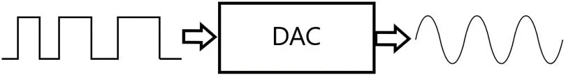
A DAC converts digital signals into continuous analog signals.
It allows the MCU to control real-world devices like audio output, motor speed control, and generate reference signals in embedded devices.
DACs are mostly used in DSPs (Digital Signal Processing), music players, mobile phones, televisions, power supplies, etc.
Types of DAC
There are various categorizations of DACs based on the method used for conversion (PWM DAC, Delta-Sigma DAC, Binary-Weighted DAC, etc.).
The most common type used in microcontrollers is R-2R Ladder DAC
An R-2R ladder DAC uses a network of just two resistor values (R and 2R) to convert digital signals into analog signals.
It's simple, compact, and easy to implement in microcontrollers.
Based on Hardware
- Internal DAC
Some microcontrollers like STM32 and ESP32 have built-in DACs. We just control them using special registers in the chip. The best part? We don’t need any extra hardware to get analog output — it’s all inside the chip!
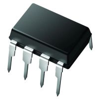
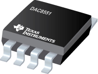
- External DAC
If our microcontroller doesn’t have a DAC or we need higher precision, we can use an external DAC chip like the MCP4921 or DAC8551. These connect to our microcontroller using communication protocols like SPI or I2C. We will need to manage the timing and voltage carefully to get accurate results.
 |  |
Key Parameters and Characteristics of DAC
Resolution:
DAC resolution is the number of distinct output levels it can produce, defined by its bit count. Each extra bit doubles the levels (e.g., 10-bit = 1024 levels). Higher resolution gives finer control, important for detailed audio, video, or analog signal output.
Maximum sampling rate:
The maximum speed at which the DAC's circuitry can operate and still produce correct output.
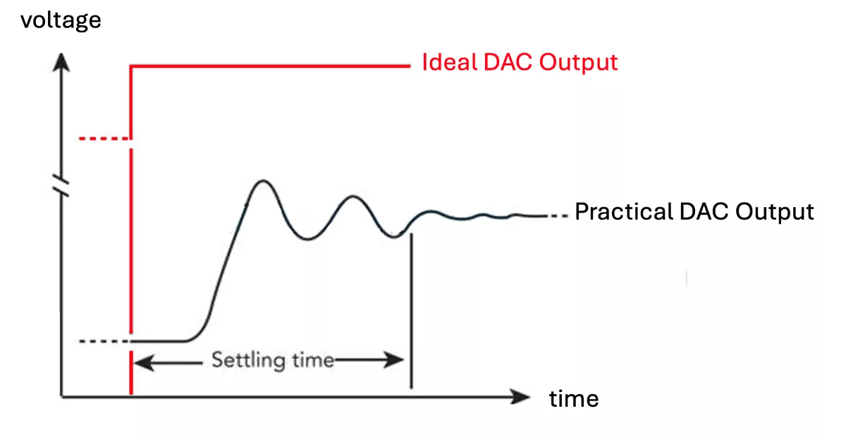
Settling Time:
Time taken for the output to stabilize after an input change.
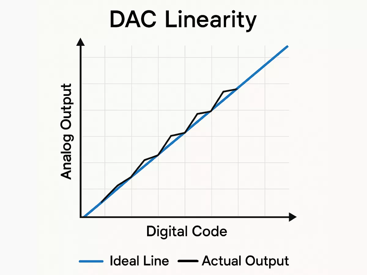
Linearity:
It measures how closely the DAC output follows a straight, ideal line as the digital input changes. High linearity means accurate and analog consistent production.
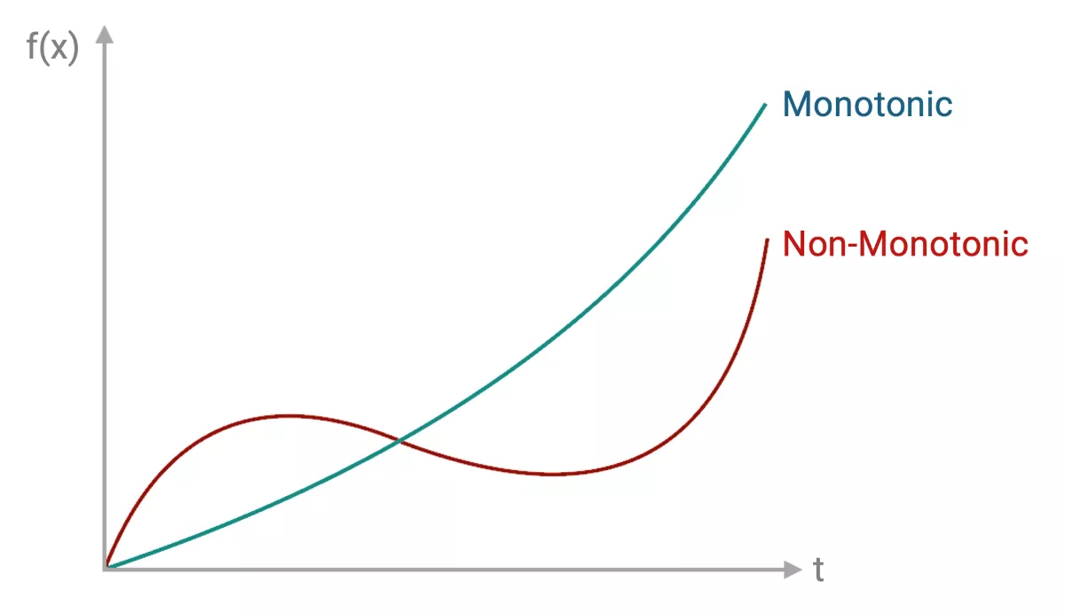
Monotonicity:
Monotonicity means the DAC output never decreases when the input increases. It ensures smooth, predictable signal changes, crucial for low-frequency generation and precise control tasks in microcontroller applications.
THD+N (Total Harmonic Distortion and Noise):
Indicates how much unwanted noise and distortion a DAC adds to the signal. In microcontroller applications, lower THD+N means cleaner analog output—important for audio or precision analog control.
Dynamic Range:
The span between the smallest and largest signals a DAC can output, measured in decibels (dB). A wider range means better detail and resolution, especially important in sensors or audio.
Phase Distortion:
Phase distortion in a DAC refers to timing errors that shift the phase of the output signal. This can affect signal integrity, especially in high-speed or communication systems where accurate timing is critical.
Jitter:
Jitter in a DAC is the small, unwanted variation in the timing of output signal transitions. It can degrade signal quality, especially in high-speed or clock-sensitive applications like audio, video, or data communication.
Understanding DAC Output: Formula and Example
A DAC converts a digital value into an analog voltage.
For an N-bit DAC with a reference voltage (Vref), the output voltage is calculated as:Vout = (D / (2^n - 1)) × Vref
Where D is the digital input (ranging from 0 to 2^n - 1).
Example:
For a 10-bit DAC (1024 steps) and Vref = 5V,
If D = 512,
Vout ≈ (512 / 1023) × 5 ≈ 2.5V
This means the DAC outputs a proportional analog voltage based on the input digital code.
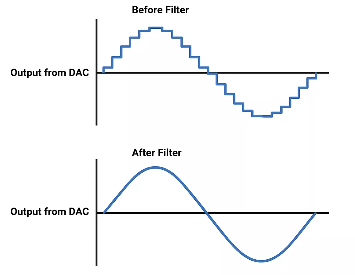
DAC Output Smoothing
DAC output often contains steps. To get a continuous analog signal, use a low-pass filter (RC filter) to smooth out.
For Example:
DAC vs PWM – What’s the Difference?
A DAC (Digital-to-Analog Converter) takes digital values and directly gives us a smooth analog output, like a steady voltage or current.
PWM (Pulse Width Modulation), on the other hand, doesn’t create a true analog signal. Instead, it sends fast on-off pulses, and if you pass that through a low-pass filter, it looks like an analog signal on average.
When to Use Which?
- Go for a DAC when we need clean, high-quality analog output, like for audio signals, precise voltage control, or anything that requires fast and accurate analog response without extra filtering.
- PWM is great when we are looking for something simple and cost-effective, like dimming LEDs, controlling motor speed, or situations where ultra-precise analog output isn’t required.
In many embedded projects, PWM with a basic low-pass filter does the job well enough—no need for extra DAC hardware unless high accuracy is a must.
Internal DAC Interfacing (microcontroller)
- Enable DAC clock
- Configure DAC pin (analog mode)
- Set resolution & reference voltage
- Write a digital value to the DAC register
- (Optional) Use DMA for continuous wave output without CPU intervention.
Many MCUs offer internal DAC:
- STM32 (F0, F3, F4, etc.) includes 12-bit DACs onboard,
- AVR (like ATmega328P) lacks DAC but uses PWM instead.
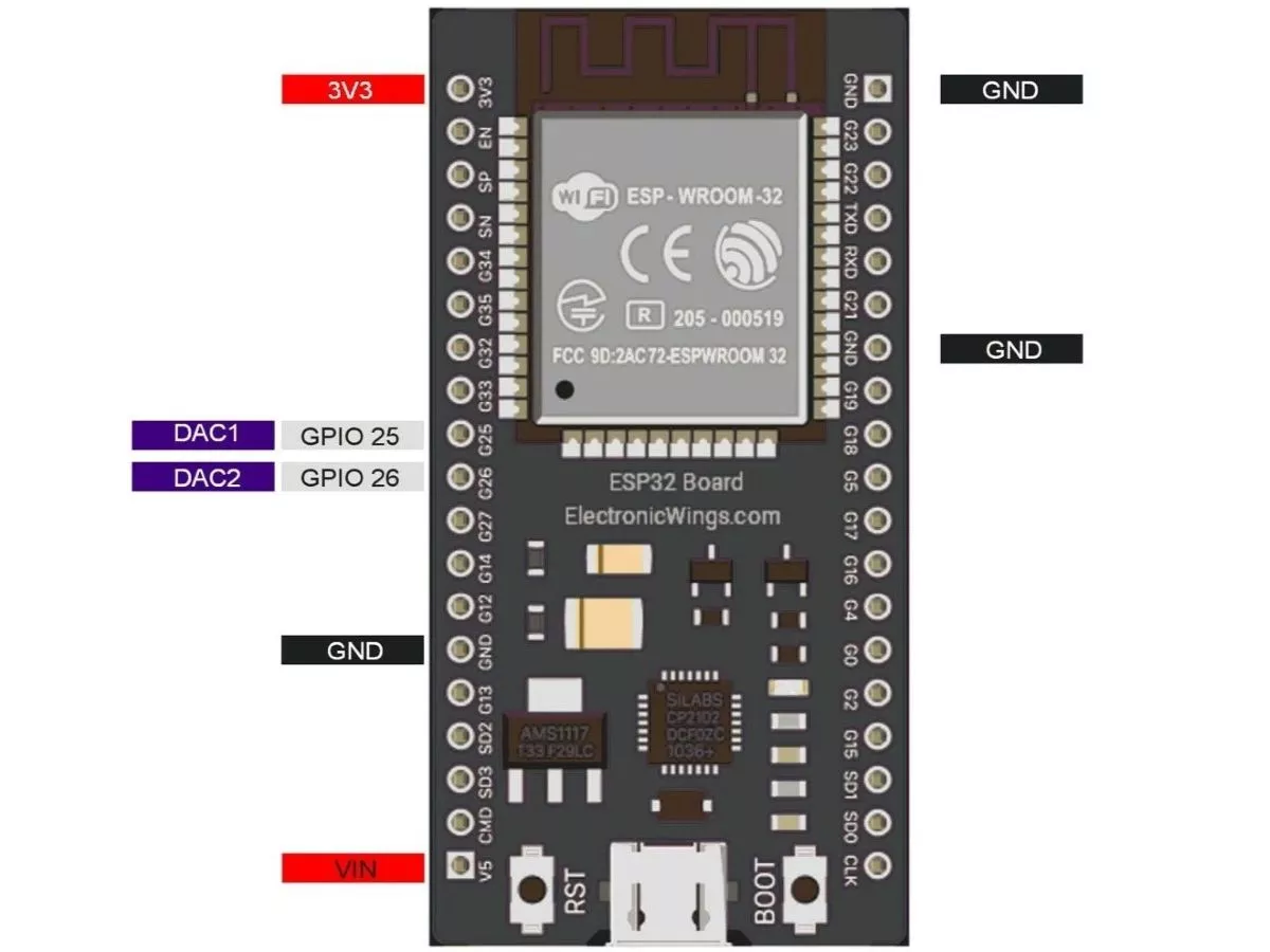
- ESP32 has 8-bit DACs on GPIO25/26
- Some PIC models include DAC functionality.
DAC in ESP32 Overview
- ESP32 has two 8-bit DAC (digital to analog converter) channels internally, which are connected to GPIO25 (Channel 1) and GPIO26 (Channel 2).
- 8-bit DAC means, ESP32 can convert the digital input (0 to 255) to an equivalent analog output.
- With 3.3Volt, our ESP32 will provide the 0-volt for digital 0 and 3.3V for digital 255. However, in practice, output by DAC is a bit lower, i.e., max 3.25V for 255.
DAC Pins of ESP32
DSO Connection Diagram with ESP32
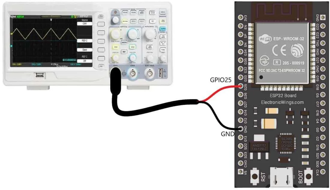
ESP32 DAC Pin Connection with DSO to visualize and analyze a real-time DAC signal generated by the ESP32 on a DSO.
Important DAC Functions in ESP32
In ESP32, there are inbuilt functions which is used to control DAC
dacWrite(pin, value)
This function is used to set the DAC value for a given pin or DAC channel.
pin: Set the DAC pin number
value: Set the value in the range of 0 - 255 (equals 0V - 3.3V).
dacDisable(pin)
This function is used to disable DAC output on a given pin or DAC channel.
pin: Set the DAC pin number
Examples
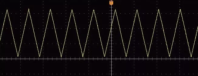
1. Triangular Wave Generation using ESP32
Let’s write some code for ESP32 to generate the triangular wave using DAC.
Code
#define DAC1 25       //Define Pin no 25 for DAC Output

void setup(){}

void loop() {
/*
* here we are using 8 bit DAC so 2^8=255
* Means 0 = 0V and 255=3.3V
*/
 for (int i=0; i<255; i++){
   dacWrite(DAC1, i);          //write on DAC Pin
 }

 for (int i=255; i>=0; i--){
   dacWrite(DAC1, i);          //write on DAC Pin
 }
}
Output
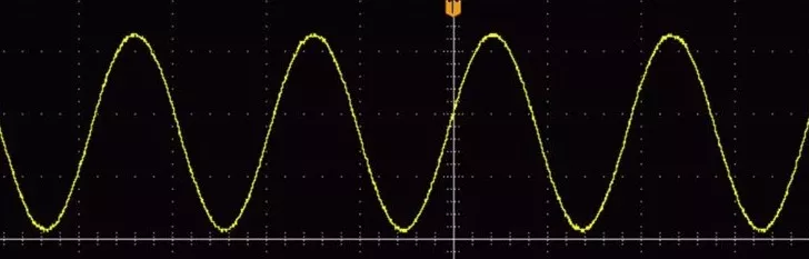
2. Sine Wave generation using ESP32
Now let’s do something interesting, let’s generate the sine wave at the output of the DAC.
Here we need to calculate the sine wave values and store them in an array of 256 values.
Code
int Sin_Array[256];                 // Define array to store sine wave values
float Period = (2*PI)/256;          // Define the sine wave conversion factor
float Rad_Angle;

void setup(){
 for(int Angle=0; Angle<256; Angle++) {
   Rad_Angle = Angle*Period;       // calculate the angle in radian
   Sin_Array[Angle] = (sin(Rad_Angle)*127)+128;  // caclulate the anagle and shift by 128
 }
}

void loop(){
 for(int i=0;i<256;i++)
   dacWrite(25,Sin_Array[i]);       // Write the sinewave vale on the DCA pin
}
Output
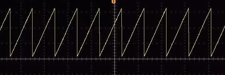
3. Sawtooth Wave generation using ESP32
Now, in this last example, let’s write some code to generate the sawtooth wave using DAC.
Code
#define DAC1 25       //Define Pin no 25 for DAC Output

void setup(){}

void loop() {
/*
* here we are using 8-bit DAC so 2^8=255
* Means 0 = 0V and 255=3.3V
*/
  for (int i=0; i<255; i++){
    dacWrite(DAC1, i);          //write on DAC Pin
  }
}
Output
Concept understood? Let's apply and learn for real