Gas Discharge Tube - GDT Quick Reference Guide
What is a GDT?
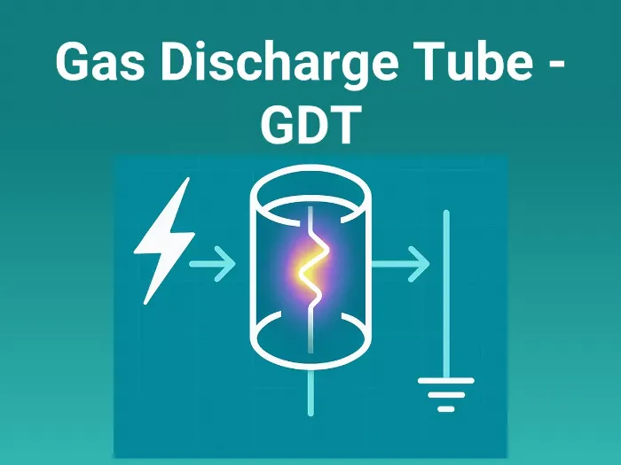
A Gas Discharge Tube (GDT) is a surge protection component used to divert large surge currents (like lightning strikes) safely to ground.
- Normally, it behaves like an open circuit (resistance in GΩ range).
- Surge condition: when voltage exceeds the sparkover threshold, the inert gas inside ionizes → becomes conductive → forms an arc discharge.
After surge: the gas de-ionizes → GDT returns to open circuit state.
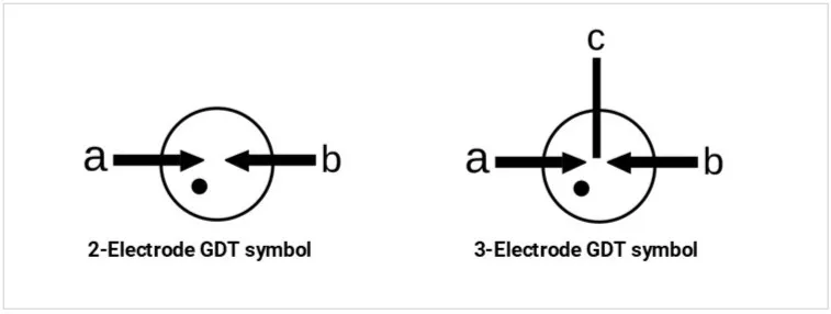
Schematic symbols:
Why GDTs are Important
- Protect circuits against extremely high-energy surges (kiloamps).
- Survive lightning transients and power cross faults where MOVs or TVS diodes would fail.
- Provide low capacitance (<2 pF) → perfect for telecom lines, RF systems, and high-speed Ethernet.
- Often used in multi-stage protection schemes (with MOVs, TVS, Polyfuses).
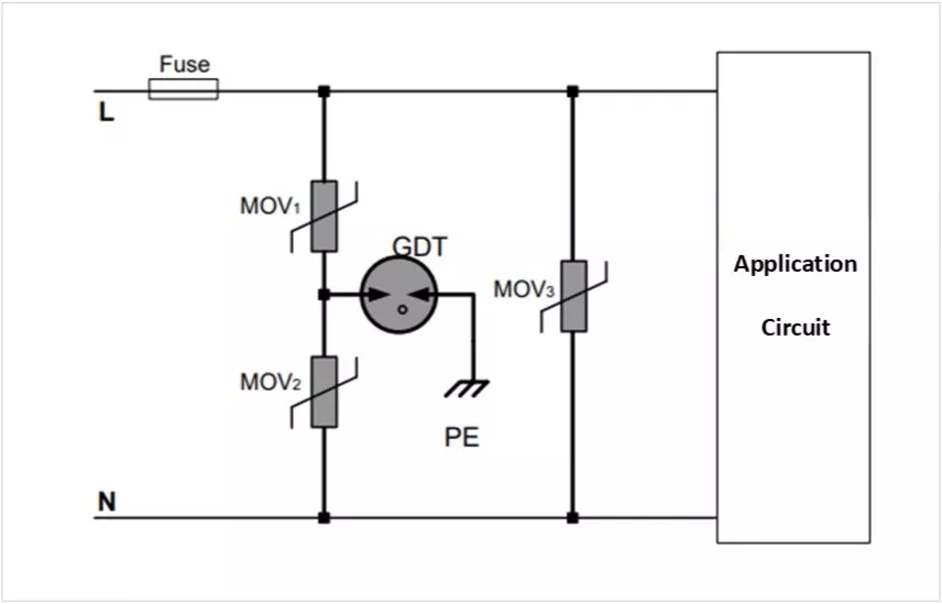
Simple GDT circuit connection:
Practical Use Cases
- Telecom lines: Telephone, DSL, Ethernet — protect from lightning surges.
- RF & Antennas: Protect base stations, radios, IoT outdoor modules.
- Industrial systems: Energy meters, wind turbines, solar inverters.
- AC mains SPD (Surge Protection Devices): Used with MOVs to handle lightning-class surges.
How It Works (Principle)
- Inside: A sealed ceramic tube filled with inert gas (argon, neon).
- Two (or three) electrodes are separated inside the tube.
- Normal operation: Gas is insulating → no current flow.
- Surge event: Surge voltage > sparkover voltage → gas ionizes → becomes plasma → conducts thousands of amps.
After surge: Voltage drops below holdover → plasma extinguishes → device resets.
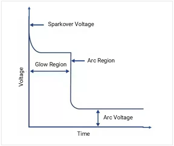
- Normal State (OFF)- Below sparkover voltage, the GDT stays insulating and does not affect normal circuit operation.
- Sparkover- When voltage exceeds the sparkover level, the gas ionizes and creates a conductive path.
- Arc State (ON)-The GDT switches ON, its voltage drops low, and surge current is diverted away from the circuit.
- Recovery- Once surge current falls below the holding level, the arc extinguishes and the GDT returns to OFF state
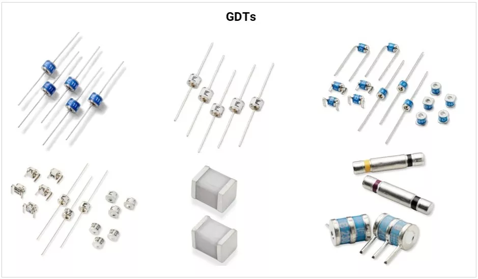
Types of GDTs
a) By Electrodes
| Type | Image | Description |
|---|---|---|
| 2-Electrode | 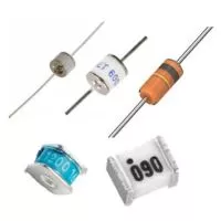 | Used between line and ground |
| 3-Electrode | 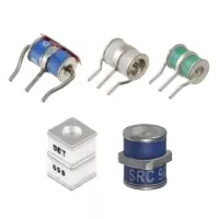 | Protect line-to-line AND line-to-ground simultaneously (ideal for telecom) |
b) By Package
- Radial leaded (through-hole): For telecom/industrial.
- Surface-mount (SMD): Compact form for Ethernet, PCB designs.
| Type | Image | Description |
|---|---|---|
| Through Hole | 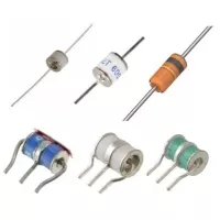 | Features standard metal wire leads. Larger, robust for industrial use. Handles massive surge currents well. |
| Surface-mount (SMD) |  | Tiny size for modern electronics. No wire leads, small footprint. Built for automated PCB assembly. |
Key Specifications (Explained Simply)
- DC Breakdown Voltage (VDC):
- Voltage where the GDT first conducts under DC.
- Must be higher than normal system voltage.
- Impulse Sparkover Voltage (Vimp):
- Actual breakdown under surge (fast-rising voltage).
- Higher than DC breakdown.
- Arc Voltage (Varc):
- Voltage across GDT during conduction (20–30 V typical).
- Ensures surge energy is safely shunted.
- Holdover Voltage:
- Voltage at which GDT continues to conduct after ionization.
- Must be above system voltage (to avoid false latching).
- Surge Current Rating (Imax):
- Maximum current GDT can handle (kiloamps).
- Capacitance:
- Very low (0.5–2 pF).
- Critical for RF/telecom — won’t distort signals.
- Response Time:
- 100 ns – µs (slower than TVS).
- That’s why GDTs are often combined with MOV/TVS.
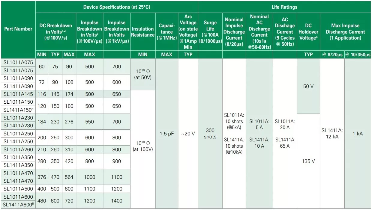
Example Littelfuse SL1411A Series Gas Discharge Tube Specifications:

Electrical Characteristics:
Real-World Design Examples
- Telecom Line (DSL/Phone):
- 230 V GDT across tip and ring.
- Paired with a PTC fuse for sustained faults.
- Ethernet Port (Outdoor PoE Switch):
- 3-electrode GDT across data pair + ground.
- Combined with a TVS diode array → protects against lightning + ESD.
- Antenna Line (RF/IoT):
- Low-capacitance GDT across coax input.
- Ensures lightning is diverted to ground without affecting RF.
- AC Mains Surge Protection Device:
- GDT + MOV combination: GDT for heavy surge, MOV for residual clamping.
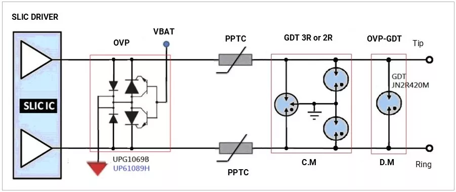
Example RJ11 Telephony Port Lightning Protection Circuit Diagram:
Advantages & Limitations
Advantages:
- Handles massive surges (lightning-class, kiloamps).
- Extremely low capacitance (RF/telecom safe).
- Very long lifetime for big surges.
- Compact and low-cost.
Limitations:
- Slower response than TVS (<ns).
- High sparkover voltage (not precise).
- Can latch as a short → must use series fuse/PTC.
- Not suitable for low-voltage IC protection alone.
Comparison with Other Devices
Feature | TVS Diode | MOV (Metal Oxide Varistor) | GDT (Gas Discharge Tube) |
|---|---|---|---|
Image |  |  | 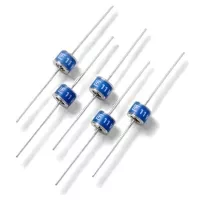 |
Response Speed | Ultra-fast (<1 ns) → ESD & fast spikes | Fast (100 ns – µs) → mains surges | Slow (µs–ms) → lightning surges |
Clamping Precision | Very precise (protects 3.3 V, 5 V, 12 V ICs) | Moderate (hundreds of volts range) | Poor (fires at 75–600 V, not exact) |
Energy Handling | Low (Watts level) | Medium–High (tens–thousands of Joules) | Very High (kiloamp lightning strikes) |
Best Application | IC-level, USB, HDMI, RS-485, automotive pins | AC mains, SMPS, automotive load dump | Telecom lines, outdoor gear, power grids |
Lifetime | Good for repeated ESD | Degrades after multiple surges (aging) | Very durable for big surges, but slow |
Key Takeaways
- GDTs are the heavyweight protectors → best for lightning surges and telecom/RF.
- Always pair with fuse/PTC (for sustained shorts) and MOV/TVS (for speed & precision).
- Use 2-electrode GDTs for line-to-ground, 3-electrode GDTs for differential lines.
- Think of GDT as the first line of defense in outdoor/industrial surge protection.
Concept understood? Let's apply and learn for real