TVS Diode Quick Reference Guide
What is a TVS Diode?
A TVS diode is a special type of diode designed to protect sensitive circuits from voltage spikes (ESD, lightning surges, switching noise).
- Under normal operation → it stays off.
- During a surge → it switches on within < 1 ns, clamping the voltage to a safe level.
- Unlike MOVs, TVS diodes are precise, fast, and designed for semiconductor-level protection.
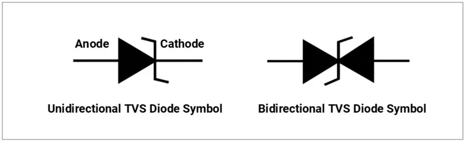
Schematic Symbols:
Why TVS Diodes are Important
Modern electronics (MCUs, USB, HDMI, automotive ECUs) run at 3.3 V / 5 V / 12 V — even a 10–20 V spike can kill them.
- TVS diodes clamp that surge instantly.
- They are used right at connectors, power rails, and data ports.
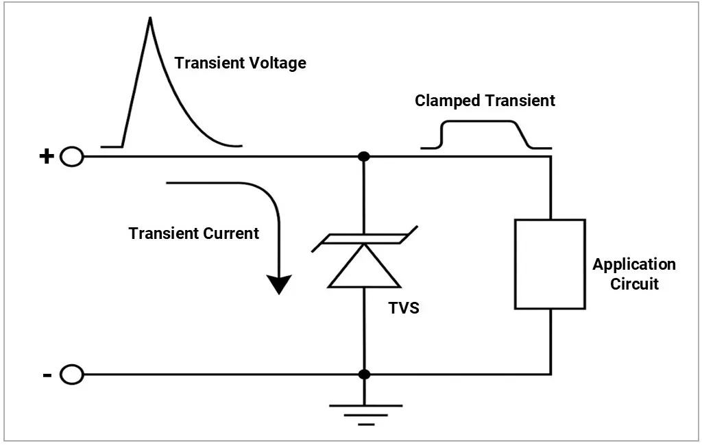
Simple TVS Diode Circuit
Practical Use Cases
- ESD protection: Human touch discharges up to 8 kV → TVS protects I/O pins.
- Automotive load dump: 12 V car battery line can surge up to 80 V → TVS clamps.
- Communication lines: RS-485, CAN bus, Ethernet → protected with TVS arrays.
- Consumer electronics: HDMI, USB, audio jacks.
- Industrial: Relay coils, PLC I/O.
Types of TVS Diodes
1) Based on Polarity
Polarity | Image | Description |
|---|---|---|
Unidirectional | 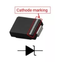 | Works like a Zener diode. Used for DC rails (e.g., 5 V supply). Symbol: Zener-like with clamping behaviour. |
Bi-directional | 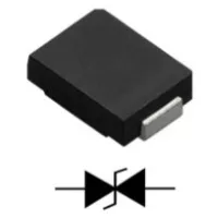 | Symmetric protection in both polarities. Used for AC signals or differential signals (USB, HDMI, CAN). Symbol: Two Zener-like diodes back-to-back. |
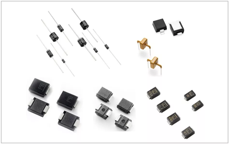
2) Based on Package / Power Rating
| Package | Image | Description |
|---|---|---|
| Through Hole | 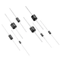 | Handles very high surge energy; used for industrial and heavy-duty protection. |
| High Power | 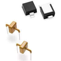 | Handles very high surge energy; used for industrial and heavy-duty protection. |
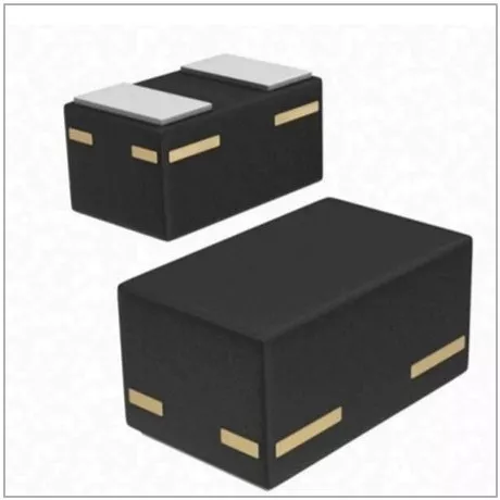
| SMD Packages | 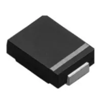 | Optimized for high-speed PCB layouts smaller footprints (like SOD-123) are for ESD, while larger ones (SMC) handle lightning or inductive surges. SOD-323, SOT-23, SMBJ, SMCJ |
| Arrays/IC Packages | 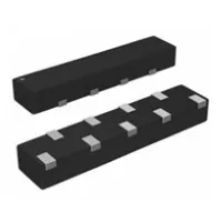 | Provides Multi-Channel Protection and space efficiency Used for High-Speed Signal Integrity (USB 3.0 or HDMI) QFN, SOT-23 arrays for USB/Ethernet. |
Key Specifications
- Maximum Stand-Off Voltage (VRWM)
- The highest continuous operating voltage the TVS can withstand without turning on.
- Always select VRWM slightly above your system’s normal voltage.
- Breakdown Voltage (VBR)
- The voltage at which the TVS begins to conduct significantly (tested at ~1 mA).
- Slightly above VRWM.
- Clamping Voltage (VC)
- The maximum voltage across the TVS during a surge at a given test current.
- This is the voltage your protected IC will see during a spike.
- Must be lower than the IC’s absolute maximum rating.
- Peak Pulse Current (IPP)
- The maximum surge current (Amps) the diode can handle for a specified waveform (usually 8/20 µs).
- Peak Pulse Power (PPP)
- Defines the energy-handling capability during a surge (IPP × VC).
- Common values: 400 W, 600 W, 1500 W, 3000 W.
- Capacitance (C)
- TVS diodes behave like small capacitors.
- High capacitance can distort high-speed signals (USB 3.0, HDMI, Ethernet).
- For high-speed lines → always use low-capacitance TVS arrays (<1 pF).
- Response Time
- TVS diodes are ultra-fast (<1 ns).
- They can catch ESD spikes that MOVs or fuses cannot.
Example F9321TR-ND TVS Diode Specafications:
Specifications | Description |
|---|---|
Direction | Bidirectional |
Maximum Stand-Off Voltage (VRWM) | 5.3V(Max) |
Breakdown Voltage (VBR) | 6.8V(Min) |
Voltage - Clamping (Max) @ Ipp | 12V |
Current - Peak Pulse | 3A (8/20µs) |
Peak Pulse Power (PPK) | 40W |
Capacitance | 0.35pF @ 1MHz |
Response Time | < 1 ns |
Package | SOD-882 |
Manufacturer | Littelfuse Inc. |
RoHS Status | ROHS3 Compliant |
Important Datasheet Curves
V-I characteristic (unidirectional vs bidirectional):
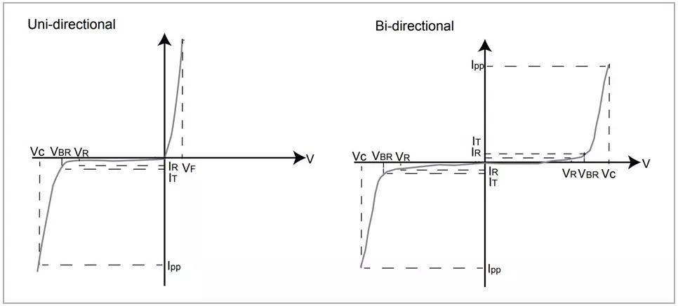
- VR Stand-off Voltage -- Maximum voltage that can be applied to the TVS without operation
- VBR Breakdown Voltage -- Maximum voltage that flows though the TVS at a specified test current (IT)
- VC Clamping Voltage -- Peak voltage measured across the TVS at a specified Ippm (peak impulse current)
- IR Reverse Leakage Current -- Current measured at VR
- VF Forward Voltage Drop for Uni-directional
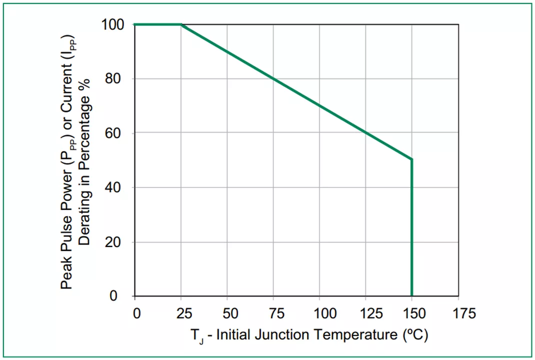
Power derating curve vs temperature.
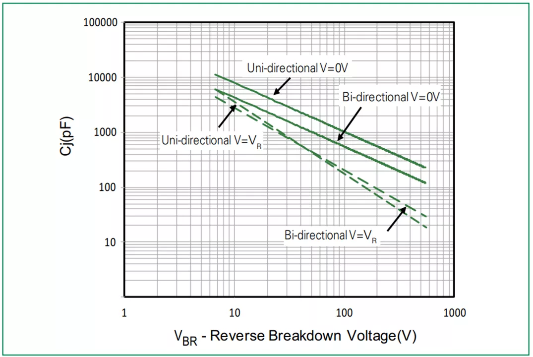
Capacitance vs bias voltage curve (for signal integrity)
How to Select a TVS Diode (Step by Step)
- Know your system voltage.
- Example: USB 5 V → choose TVS with VRWM ≥ 5 V.
- Check IC's max voltage rating.
- Ensure TVS VC is below IC max rating.
- Check power rating.
- Choose the PPK rating based on the expected surge environment (e.g., 600 W for USB, 1500 W for automotive).
- Choose unidirectional or bidirectional.
- DC rail → unidirectional.
- AC/differential (USB, HDMI) → bidirectional.
- Check capacitance.
- High-speed signals need <1 pF.
- Power lines can tolerate higher capacitance.
Application Circuit Diagrams
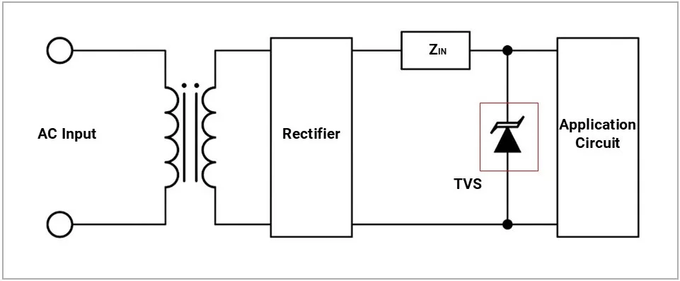
- TVS Diode Overvoltage Protection Circuit Diagram
TVS diode across the DC input rail.
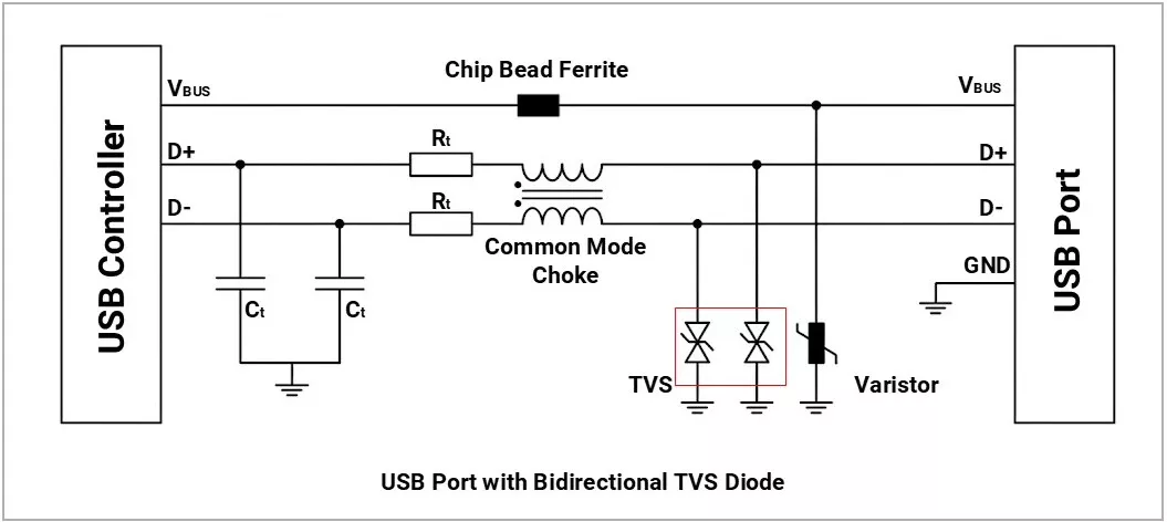
- USB Port Circuit Protection Using Bidirectional TVS Diodes
- TVS array across D+/D− lines.
Failure Modes
A TVS diode primarily fails as a short circuit
- Short circuit: diode permanently conducts → rail gets clamped.
Comparison with Other Devices
Different surge protection devices exist, each with its strengths and trade-offs. TVS diodes are typically used for fast, precise IC protection, while MOVs and GDTs are chosen for higher-energy surges like mains spikes or lightning.
Feature | TVS Diode | MOV (Metal Oxide Varistor) | GDT (Gas Discharge Tube) |
|---|---|---|---|
Image | 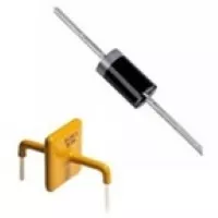 | 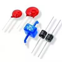 | 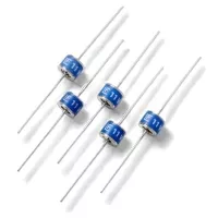 |
Response Speed | Ultra-fast (<1 ns) → ESD & fast spikes | Fast (100 ns – µs) → mains surges | Slow (µs–ms) → lightning surges |
Clamping Precision | Very precise (protects 3.3 V, 5 V, 12 V ICs) | Moderate (hundreds of volts range) | Poor (fires at 75–600 V, not exact) |
Energy Handling | Low (Watts level) | Medium–High (tens–thousands of Joules) | Very High (kiloamp lightning strikes) |
Best Application | IC-level, USB, HDMI, RS-485, automotive pins | AC mains, SMPS, automotive load dump | Telecom lines, outdoor gear, power grids |
Lifetime | Good for repeated ESD | Degrades after multiple surges (aging) | Very durable for big surges, but slow |
- Basically
- TVS = fast IC protection, MOV = mains/automotive surge absorber, GDT = heavy lightning defense.
- TVS vs Zener diode:
- TVS is designed for surge absorption, not regulation.
- Zener is for a steady-state voltage reference.
Common mistakes to avoid
- Selecting VRWM too close to system voltage → causes unwanted conduction
- Ignoring clamping voltage (VC) → protected IC may still get damaged
- Choosing insufficient power rating (PPP) → diode fails during surge
- Using wrong type (unidirectional vs bidirectional) for the application
- Placing TVS far from connector/input → reduces protection effectiveness
- Poor grounding/layout → increases clamping voltage due to inductance
- Using high-capacitance TVS on high-speed lines → signal distortion
- Assuming one TVS protects all lines → mismatched protection levels
- Not checking datasheet waveforms (ESD, 8/20 µs, etc.)
- Ignoring long-term degradation from repeated surgesv
Concept understood? Let's apply and learn for real