Polyfuse Quick Reference Guide
What is a Polyfuse?
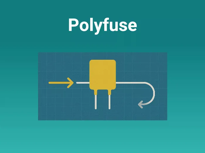
A Polyfuse (also called a Resettable Fuse or PPTC device) is a polymeric positive temperature coefficient device used for resettable overcurrent protection.
- At normal current → very low resistance → circuit runs normally.
- At fault current/short → device heats up → resistance increases sharply → limits current flow (like an open fuse).
- When the fault is cleared, and power is removed → it cools and resets, ready for reuse.
Key difference from a normal fuse: A glass fuse must be replaced once blown, while a Polyfuse resets automatically.
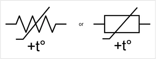
Schematic Symbols of Polyfuse:
Why Polyfuses are Important
- Prevent damage from overcurrent and short circuits.
- Save cost and downtime → no need for manual replacement.
- Provide user-friendly protection in consumer and embedded products.
- Essential for meeting safety and USB/IEC standards in many devices.
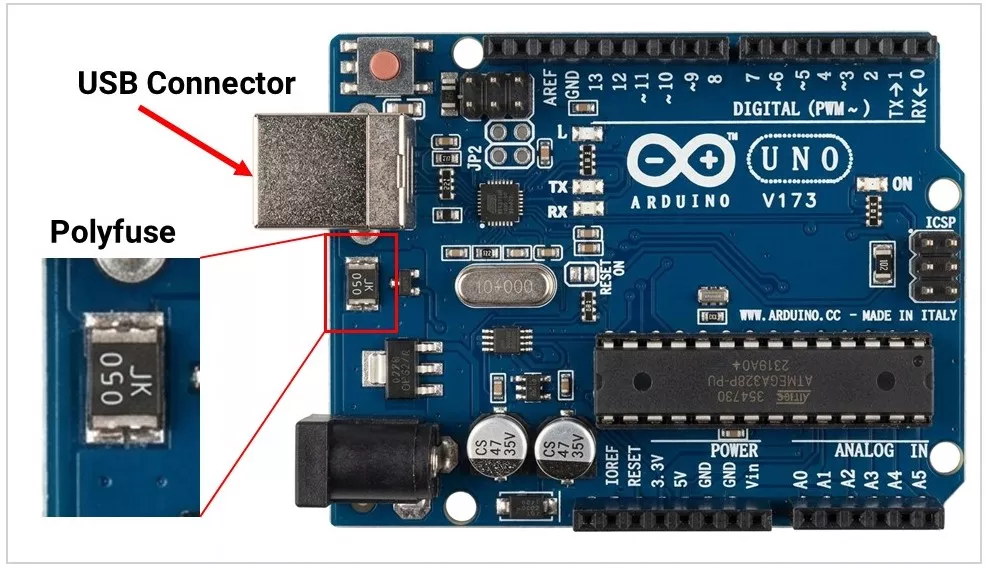
Real-world example:
- In a USB port, if a user connects a faulty cable drawing >1 A, the Polyfuse trips → saves the motherboard without blowing permanently.
Practical Use Cases
- USB ports – resettable protection against shorts.
- Battery packs (Li-ion) – protect cells from overcurrent or runaway.
- Consumer devices – toys, cameras, chargers, IoT nodes.
- Telecom & networking – line cards, Ethernet ports.
- Automotive & Industrial – ECUs, infotainment, instrument clusters.
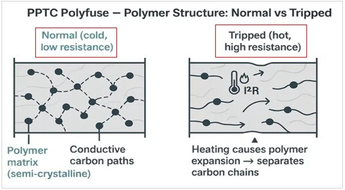
How It Works (Principle)
- Constructed from a polymer matrix with conductive carbon particles.
- Normal condition: Carbon paths conduct → device acts like a low-resistance resistor.
- Overcurrent condition: Current heats polymer → expansion separates carbon particles → resistance rises rapidly (hundreds of ohms) → limits current.
- Cooling/reset: When power is removed and device cools, the carbon paths reconnect → low resistance restored.
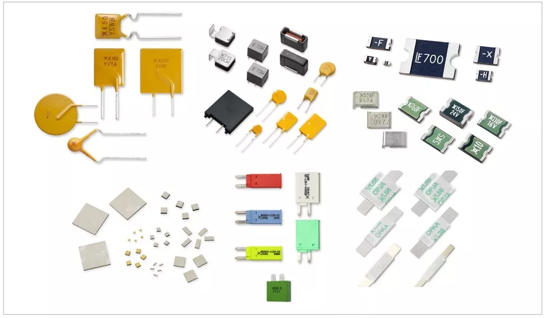
Types of Polyfuses
| Types | Images | Description |
|---|---|---|
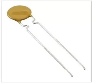
| Radial Leaded | 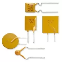 | Through-hole mounting. Used in adapters, chargers, and battery packs. |
| Surface Mount | 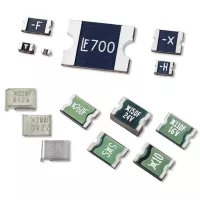 | Compact footprint (SMD package- 1206, 1812, 2920). Used in USB ports, portable electronics, and telecom boards. |
| High-Hold Automotive/Industrial | 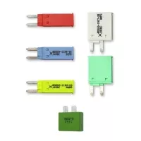 | Designed for higher voltage/current. |
| Battery straps | 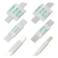 | Welds directly to battery cells. Resets when it cools. Stops battery pack fires. |
Key Specifications (Explained Simply)
- Hold Current (Ihold):
- The maximum continuous current the device can carry without tripping.
- Trip Current (Itrip):
- Current at which the device “trips” into high resistance.
- Time-to-Trip:
- The time it takes to respond once Itrip is reached.
- Can be ms to seconds (not instant like TVS diodes).
- Rated Voltage (Vmax):
- The maximum circuit voltage it can withstand.
- Initial Resistance (Rmin, Rmax):
- Device resistance before tripping.
- Important for low-voltage circuits (USB, battery packs).
- Post-Trip Resistance (R1):
- Resistance after tripping (very high, limits current).
- Power Dissipation (Pd):
- Heat is generated in normal operation.
- Reset Cycles:
- Can reset hundreds–thousands of times, but resistance increases slightly with age.
Example Littelfuse PolySwitch RHEF series Ployfuse Specifications:
| Type | Description |
|---|---|
| Manufacturer | Littelfuse Inc. |
| Type | Polymeric |
| Voltage - Max | 16V |
| Current - Hold (Ih) (Max) | 2 A |
| Current - Trip (It) | 3.8 A |
| Current - Max | 100 A |
| Time to Trip | 4.3 s |
| Resistance - Initial (Ri) (Min) | 45 mΩ |
| Resistance - Post Trip (R1) (Max) | 110 mΩ |
| Operating Temperature | -40°C ~ 125°C |
| Mounting Type | Through Hole |
| Package / Case | Radial, Disc |
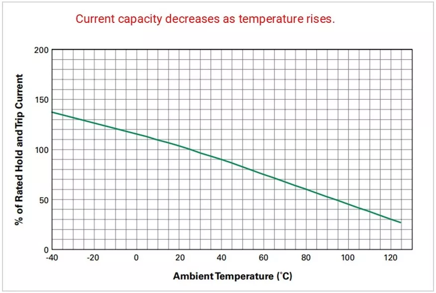
Example Polyfuse Temperature Rerating Curve:
How to select PPTC
- Define normal operating current (Ihold): Choose a PPTC with hold current higher than your circuit’s maximum steady current so it doesn’t trip during normal operation.
- Check trip current (Itrip): Ensure the trip current is below the fault current level, so the fuse reliably activates during overload or short-circuit conditions.
- Match voltage rating: Select a device with a maximum voltage rating equal to or higher than your circuit voltage.
- Consider ambient temperature: PPTC performance changes with temperature, so apply derating if the device operates in high-temperature environments.
- Evaluate resistance (Rinitial): Lower resistance reduces voltage drop and power loss during normal operation.
- Verify response time and reset behavior: Ensure the trip time suits your protection needs and that the reset characteristics match how quickly the circuit should recover.
Advantages & Limitations
Advantages:
- Resettable → no replacement
- Low cost, small size
- Perfect for user-accessible ports (USB, chargers).
Limitations:
- Slower response (ms) → cannot catch fast spikes (use TVS diodes instead).
- Resistance increases after every trip (aging).
- Degradation Over Cycles: PPTCs have a limited "trip cycle" life. Repeated tripping causes thermal stress on the polymer matrix, which can lead to permanent changes in trip characteristics or eventual failure.
Key Takeaways for Engineers
- Polyfuses protect against overcurrent — not voltage surges.
- Always combine with TVS diodes or MOVs for complete protection.
- Perfect for resettable user-accessible protection (USB ports, batteries).
- Always check Ihold vs system current and Itrip vs fault current
Concept understood? Let's apply and learn for real