
Logic Gates Quick Reference Guide
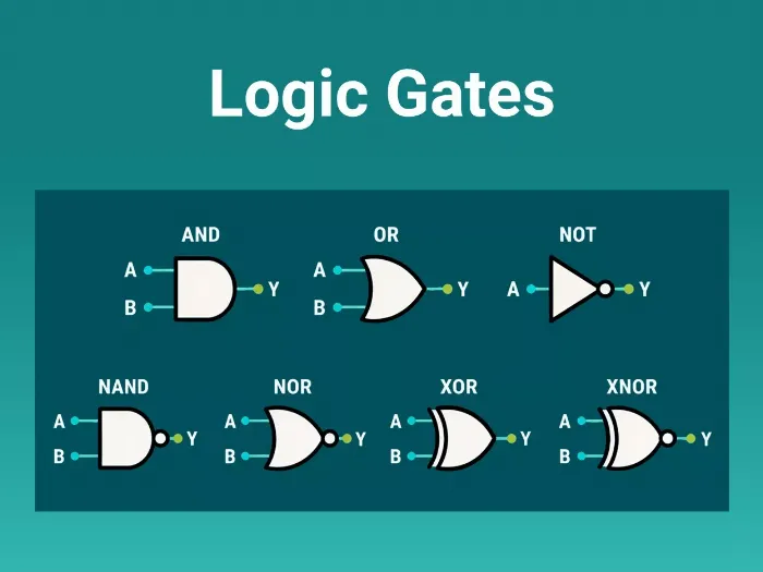
Logic gates are the basic building blocks of digital circuits. They receive one or more binary inputs and generate a binary output.
Binary values:
In positive logic:
- 0 = LOW, False
- 1 = HIGH, True
Basic Logic Gates
AND Gate
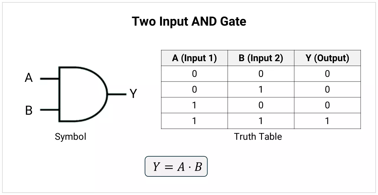
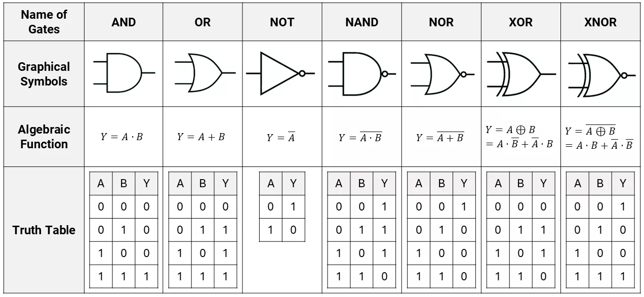
An AND gate produces 1 only when all inputs are 1.
OR Gate
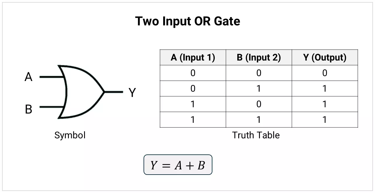
An OR gate produces 1 when at least one input is 1.
NOT Gate
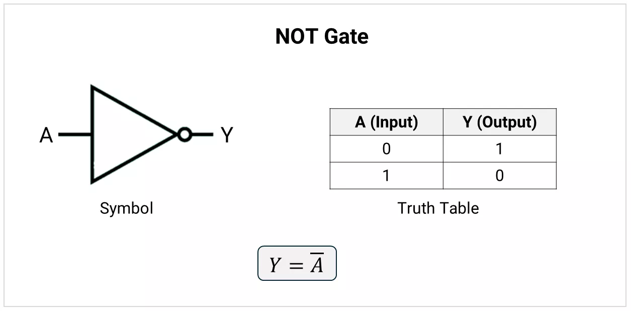
A NOT gate produces the complement of its input. It is also called an inverter.
Universal Logic Gates
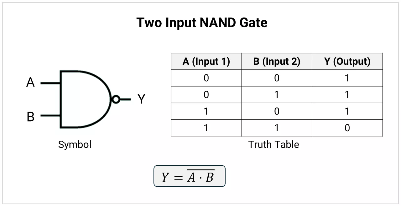
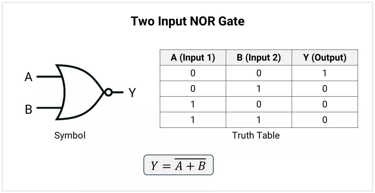
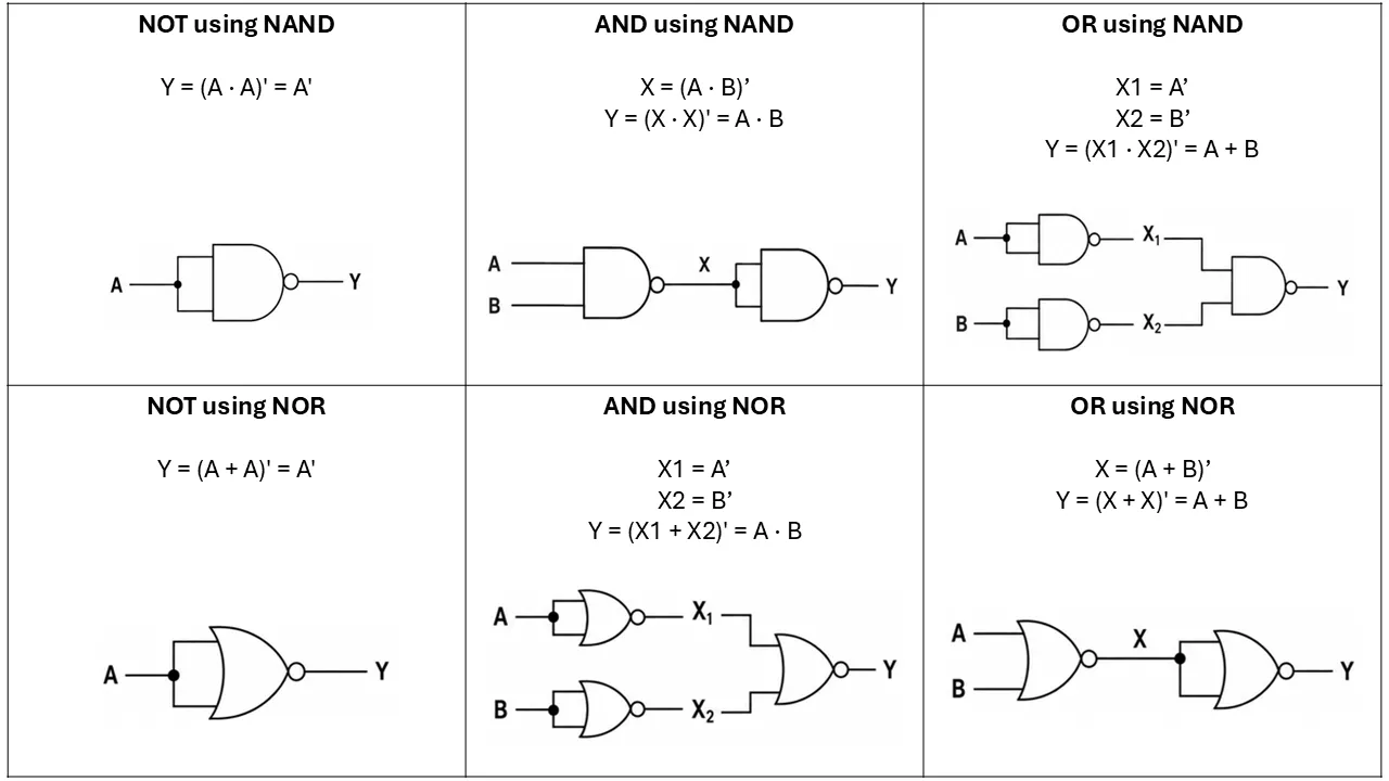
NAND and NOR are universal gates. Either NAND gates alone or NOR gates alone can implement any Boolean function.
NAND Gate
A NAND gate is an AND gate followed by a NOT operation.
NOR Gate
A NOR gate is an OR gate followed by a NOT operation.
Exclusive Logic Gates
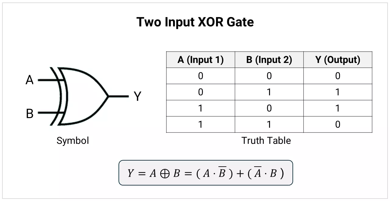
XOR Gate
A two-input XOR gate produces 1 when its inputs are different.
Common uses:
- Sum generation in adders
- Parity generation
- Bit comparison
- Controlled bit inversion
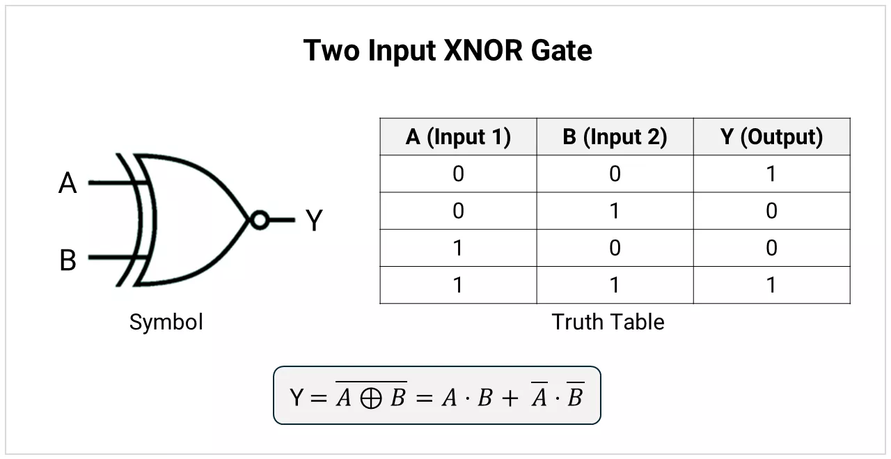
XNOR Gate
A two-input XNOR gate produces 1 when its inputs are equal.
Common uses:
- Equality comparison
- Digital comparators
- Bit-match detection
- Data matching circuits
All Logic Gates Summary Table
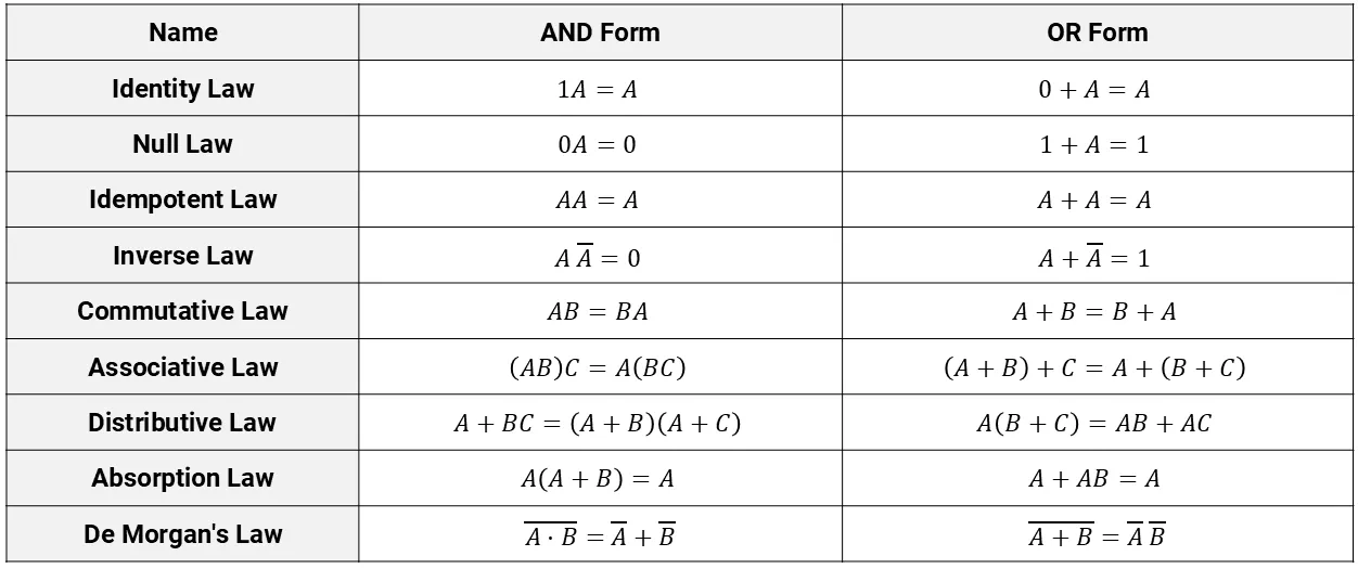
Boolean Algebra Laws and Rules:
Implementing Basic Gates (NOT, AND, OR) using Universal Gates
Universal gates recreate AND, OR, and NOT by using tied inputs or by adding an inversion stage.
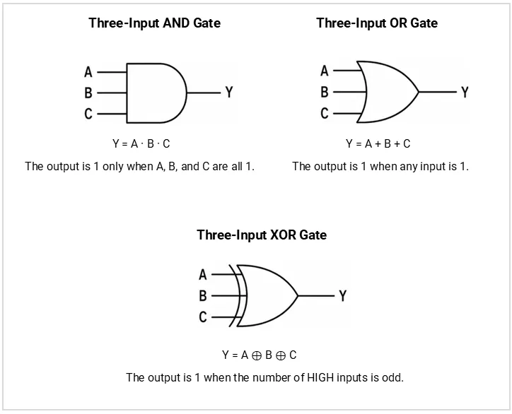
Multi-Input Gates
- AND, OR, NAND, and NOR gates commonly have multiple inputs.
- Multi-input XOR produces 1 when the number of HIGH inputs is odd, while multi-input XNOR produces 1 when the number of HIGH inputs is even.
- A NOT gate always has one input.
Common Applications
Logic gates are used in:
- Adders and subtractors
- Multiplexers and decoders
- Comparators
- Registers and counters
- Memory circuits
- Alarm and safety systems
- Control circuits
- Arithmetic logic units
Concept understood? Let's apply and learn for real