Optocoupler Quick Reference Guide
What is an Optocoupler?
An optoelectronic device that transfers electrical signals between two isolated circuits using light.
Since the two sides are connected only by light, no wires, no common ground, optocouplers provide galvanic isolation, protecting low-voltage microcontrollers from high voltages, spikes, and noise.
Why Optocouplers Are Important
- Safety: Provides the complete isolation between input and output.
- Noise Isolation: Blocks spikes, surges, and EMI from industrial equipment.
- Level Shifting: Interfaces 3.3V MCUs with 12V/24V/230V circuits.
- Protection: MCU stays safe while controlling relays, triacs, or MOSFETs.
Practical Use Cases
- Microcontroller ↔ High Voltage Interface (e.g., driving triacs, MOSFETs, relays safely).
- Switching Power Supplies – feedback path from secondary to primary side.
- Industrial Control – isolate sensors, communication lines from noise/surges.
- Medical Electronics – Patient safety by isolating patient-connected circuits from high-voltage power supplies.
- Digital Communication Isolation – UART, I²C, or CAN bus across noisy domains.
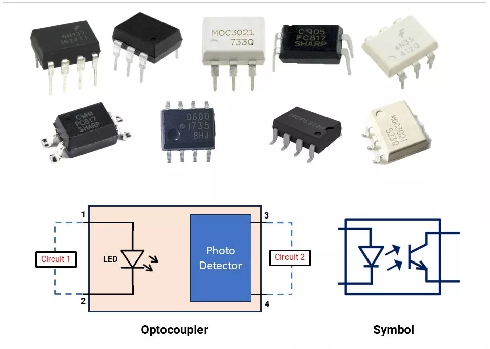
Internal Structure & Working
- LED emits IR light when forward-biased.
- Detector (phototransistor/photodiode/etc) picks it up → converts into electrical current.
- Key point: Circuits share no electrical connection, only optical coupling.
Types of Optocouplers
| Type | Image | Description |
|---|---|---|
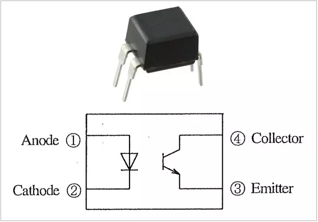
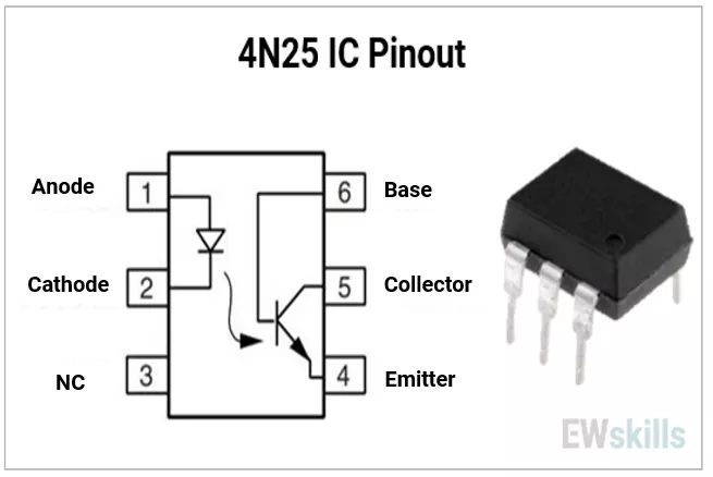
| Phototransistor Output | 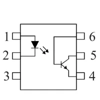 | Most common type (4N25, PC817). Used for general signal isolation. Moderate speed (~10–100 µs). |
| Photodarlington Output |
 | Photodarlington: Higher gain, slower speed. |
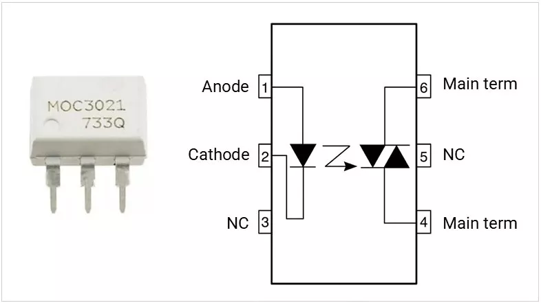
| Phototriac Output | 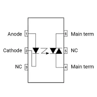 | For AC mains control (MOC3021, MOC3063). With/without zero-cross detection. |
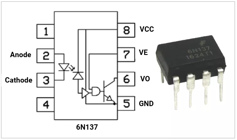
| High-Speed Logic Optos | 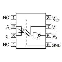 | TTL/CMOS compatible (6N137, HCPL-2631). Used for digital communication signals (UART, CAN, digital comms). |
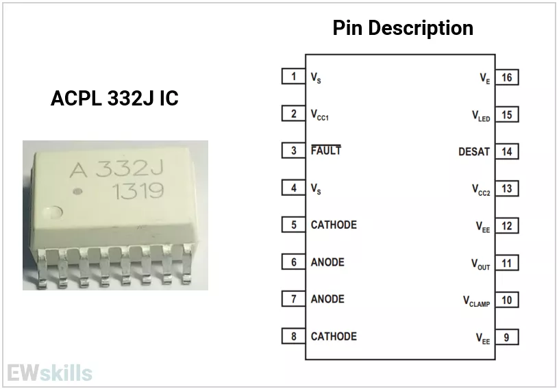
| MOSFET/IGBT Driver Optos | 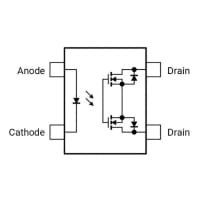 | High current isolated gate drivers (e.g., HCPL-3120, ACPL-332J). Used in motor drives, inverters, and power electronics. |
Packages & Pinouts
1)Through-Hole (DIP) Packages
| Package Sub-Type | Image Reference | Example / Description |
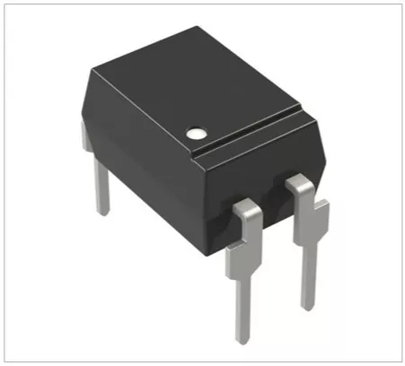
| DIP-4 | 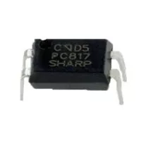 | 4-pin Dual In-line Package (e.g., PC817). Common for basic signal isolation. |
| DIP-6 | 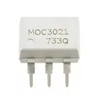 | 6-pin Dual In-line Package (e.g., MOC3021). Often used for phototriac outputs. |
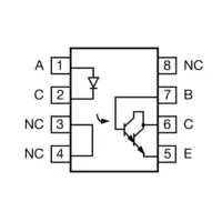
| DIP-8 | 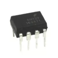 | 8-pin Dual In-line Package (e.g., 6N137). Common for high-speed logic optocouplers. |
| DIP-16 | 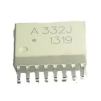 | 16-pin Dual In-line Package (e.g., TLP521-4, ACPL-332J). Used for multi-channel optocouplers or complex gate drivers. |
2)Surface-Mount (SMD / SOIC) Packages
| Package Sub-Type | Image Reference | Example / Description |
| SOIC-4 | 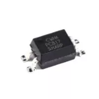 | 4-pin Small Outline IC (e.g., PC817). Compact surface-mount equivalent of the DIP-4. |
| SOIC-6 | 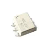 | 6-pin Small Outline IC (e.g., MOC3021). Compact surface-mount equivalent of the DIP-6. |
| SOIC-8 NB | 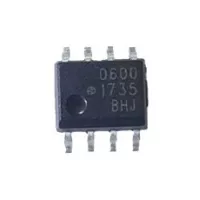 | 8-pin Narrow Body Small Outline IC. Compact profile for standard surface-mount designs. |
| SOIC-8 WB | 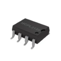 | 8-pin Wide Body Small Outline IC (e.g., HCPL3120). Wider footprint, often required for higher voltage isolation clearances in motor drives and power electronics. |
Key Specifications (Datasheet Parameters)
- CTR (Current Transfer Ratio)- % of output current relative to input LED current.
- Ratio: Iout / Iin × 100%.
- Typical: 50–600%.
- Depends on input LED current, temperature, and aging.
- Isolation Voltage (Vrms)- Voltage withstand between input & output.
- Typical: 2.5kV – 5kV.
- Input LED Specs
- Forward Voltage (VF): ~1.2V typical.
- Forward Current (IF): 5–20mA.
- Output Specs
- Collector-Emitter Voltage (Vceo).
- Saturation Voltage (Vce(sat)) vs load current.
- Switching Speed
- Rise/fall times, propagation delay.
Fast optos: <100ns. - Regular phototransistor optos: tens of µs.
- Rise/fall times, propagation delay.
- Temperature Dependence
- CTR decreases with rising temperature.
- Derating curves are provided in datasheets.
- Safety Standards – UL, VDE certification for isolation.
Example PC817X Series (PC817X_NSZ9F) Optocoupler Specifications:
| Specification | Value |
|---|---|
| Current Transfer Ratio (CTR) | 50% to 600% (at I_F = 5mA, V_CE = 5V) |
| Isolation Voltage (Vrms) | 5000 Vrms (5.0 kV) |
| Input LED Forward Voltage (V_F) | 1.2V Typical, 1.4V Maximum (at I_F = 20mA) |
| Input LED Forward Current (I_F) | 50 mA (Absolute Maximum Rating) |
| Output Collector-Emitter Voltage (V_CEO) | 80V (Absolute Maximum Rating) |
| Output Saturation Voltage (V_CE(sat)) | 0.1V Typical, 0.2V Maximum (at I_F = 20mA, I_C = 1mA) |
| Switching Speed (Rise Time - t_r) | 4 µs Typical, 18 µs Maximum (at V_CE = 2V, I_C = 2mA, R_L = 100Ω) |
| Switching Speed (Fall Time - t_f) | 3 µs Typical, 18 µs Maximum (at V_CE = 2V, I_C = 2mA, R_L = 100Ω) |
| Temperature Range (Operating) | -30°C to +100°C (Power dissipation and forward current require derating above 25°C) |
| Safety Standards & Approvals | UL Approved / Recognized, RoHS Directive Compliant |
CTR Curves and Design Notes
- CTR vs Input Current:
- Higher IF → more output current, but LED stress increases.
- CTR vs Temperature:
- CTR falls at higher temps (e.g., −50% at 100°C).
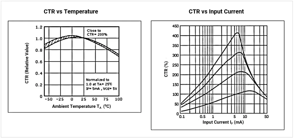
- Aging: LED brightness drops with time → CTR reduces.
- Design Rule: Always design with worst-case CTR (minimum guaranteed in datasheet).
Real-World IC Examples
1) PC817 (Sharp / Everlight): Most common low-cost opto. (Click Here)
2) MOC3021(ON Semi): Triac driver for AC loads. (Click here)
3) 4N35 / 4N25: Classic phototransistor optos. (Click Here)
4) 6N137 / HCPL-2631: High-speed logic isolation. (Click Here)
5) HCPL-3120 / ACPL-332J: Gate driver optos for IGBTs/MOSFETs. (Click Here)
Application Circuits and Circuit Connections
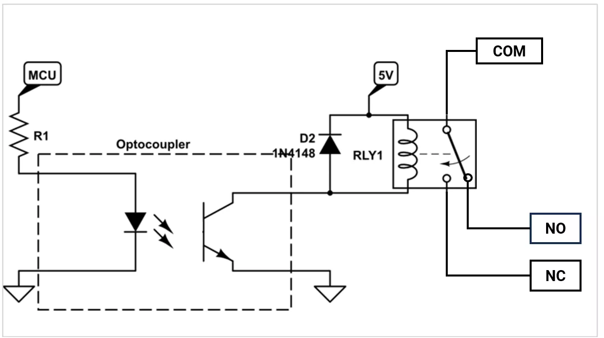
1) MCU to Relay Isolation
- PC817 drives the transistor → relay coil.
- MCU → Opto → NPN transistor → Relay coil.
- Flyback diode across the coil.
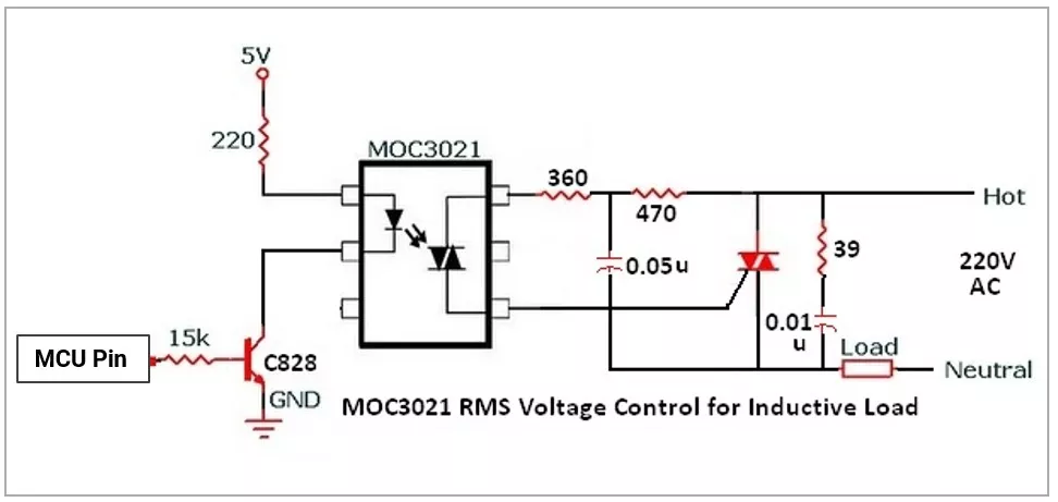
2) AC Lamp/Fan Control
- MOC3021 + Triac + Snubber → AC dimming.
- MCU → MOC3021 → TRIAC → AC Load.
- Snubber circuit for inductive loads.
Design Guidelines
- Choose opto type for application (switching vs AC vs comms).
- Drive LED at nominal IF (10mA typical) but check CTR min.
- Use pull-up resistors on transistor outputs.
- Maintain PCB creepage/clearance for isolation.
- For high-reliability apps: use dual optocouplers (redundancy).
Testing & Troubleshooting
- Check the LED forward voltage with a multimeter (diode mode).
- Check CTR by applying known IF and measuring output current.
- Common failures:
- LED burnout (overcurrent).
- CTR degradation (aging).
- Breakdown of insulation (overvoltage).
Selection Checklist
Here is the quick-reference checklist for selecting an optocoupler:
- Isolation: Check the isolation voltage rating and required creepage/clearance for your safety standards.
- Current Transfer Ratio (CTR): The output-to-input current ratio. Always design for the minimum CTR over the component's lifespan and temperature range.
- Output Type: Choose Phototransistor (general use), Photodarlington (high current, slow), Logic Gate (high-speed data), or Phototriac (AC loads).
- Output Ratings: Ensure the breakdown voltage exceeds your load supply voltage, and the max continuous current meets your load demands.
- Input Drive: Verify your microcontroller can source/sink the required LED forward current and account for the forward voltage drop.
- Speed/Bandwidth: Check the turn-on/turn-off times or baud rate to ensure it can handle your signal frequency (PWM, SPI, UART).
- Operating Environment: Verify the operating temperature range and select the appropriate package (SMD, DIP) for your board layout.
Concept understood? Let's apply and learn for real