Switch Quick Reference Guide
What is a Switch?
A switch is an electromechanical device that opens or closes an electrical circuit, controlling current flow.
Think of it as a manual gate for electricity — ON means current flows, OFF means it doesn’t.
Why Switches Are Important in Embedded Applications
Switches are the primary user interface in many systems, from a power ON/OFF button to a microcontroller reset pin.
They provide:
- User input (mode select, menu navigation)
- Control (power enable/disable)
- Maintenance functions (reset, programming mode)
- Safety interlocks (door sensors, emergency stop)
Practical note: In embedded products, switches often carry logic-level signals to MCUs, but sometimes handle power switching too, which changes their rating requirements.
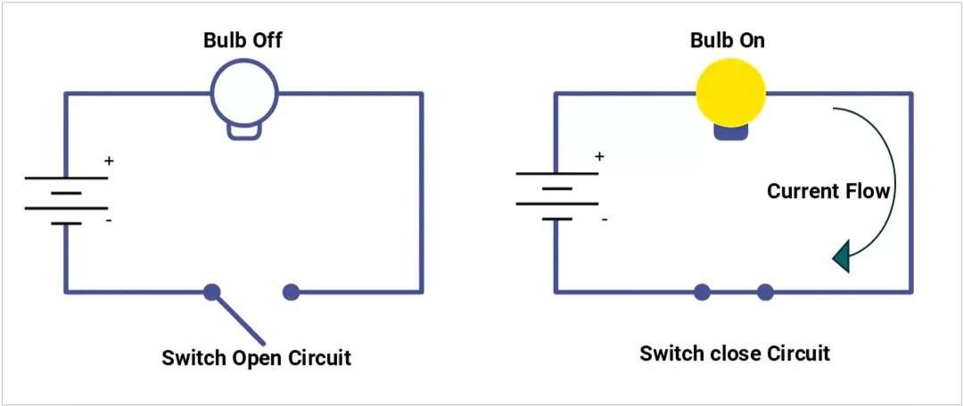
How a Switch Works
- Contacts: Metal surfaces that touch to close the circuit.
- Actuator: The part you press, toggle, or slide.
- Housing: Protects the mechanism.
Switch Operation Types | Image | Description |
|---|---|---|
Momentary | 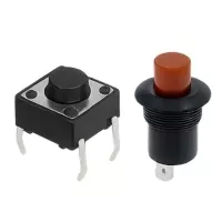 | Works only while pressed (e.g., reset switch). |
Maintained (latching) | 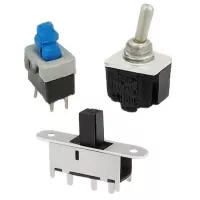 | Stays in the last position until changed (e.g., light switch). |
Switch Types
1) By Contact Configuration
| Name | Symbol | Example Use |
|---|---|---|
Single Pole Single Throw (SPST) | 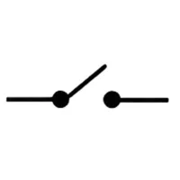 | Simple ON/OFF |
Single Pole Double Throw (SPDT) | 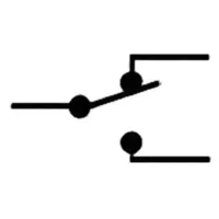 | Select between two signals |
Double Pole Single Throw (DPST) | 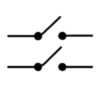 | Control two circuits at once |
Double Pole Double Throw (DPDT) | 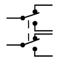 | Two SPDTs linked |
2) By Actuation
| Type | Image | Description |
|---|---|---|
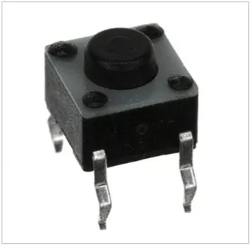
Tactile Switch (e.g., Omron B3F) | 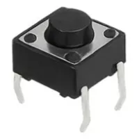 | Compact, momentary, SMD or THT, used for menu buttons. |
| Pushbutton | 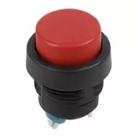 | Larger, panel-mount, momentary or maintained. |
| Toggle Switch | 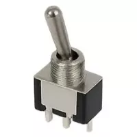 | Lever-type, maintained, for power/mode selection. |
| Rocker Switch | 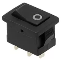 | Common in mains power panels. |
| Slide Switch | 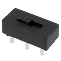 | Mode selection in small devices. |
| DIP Switch | 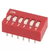 | Sets configuration bits, replaces jumpers. |
| Rotary Switch | 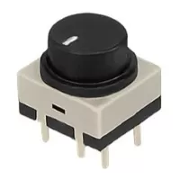 | Multiple position selector (e.g., fan speed control). |
| Reed Switch | 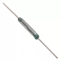 | Magnetic actuation, used in door sensors. |
| Membrane Switch | Flat, sealed, used in keypads. | |
| Microswitch | 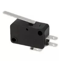 | Snap-action, high durability (mouse buttons, limit switches). |
3) By Mounting
| Type | Image | Description |
|---|---|---|
| Through Hole Mount | 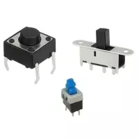 | Durable, replaceable, suited for power circuits |
| Surface Mount | 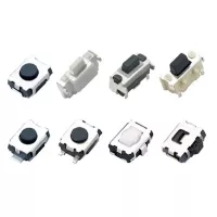 | Compact, reflow-solderable, for automated assembly. |
| Panel Mount | 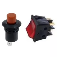 | Designed for user-facing controls. |
Key Specifications
Electrical:
- Contact Rating – Max voltage & current (e.g., 50mA @ 12VDC for a tactile switch).
- Contact Resistance – Lower is better (<100 mΩ typical).
- Insulation Resistance – Typically >100 MΩ.
- Bounce Time – Delay before stable contact (1–20 ms).
Mechanical:
- Operating Force – Force needed to actuate (e.g., 160g for Omron B3F tactile).
- Travel Distance – How far the actuator moves before closing contact.
- Life Expectancy – Measured in cycles (e.g., 1M actuations for tactile switches).
Example FSMJ series Tactile Switch specifications:
| Type | Description |
|---|---|
| Category | Switches Tactile Switches |
| Mfr | TE Connectivity ALCOSWITCH Switches |
| Series | FSMJ |
| Packaging | Bulk |
| Circuit | SPST-NO |
| Switch Function | Off-Mom |
| Contact Rating @ Voltage | 0.05A @ 24VDC |
| Actuator Type | Standard |
| Mounting Type | Through Hole |
| Actuator Height off PCB, Vertical | 5.00mm |
| Actuator Orientation | Top Actuated |
| Outline | 6.00mm x 6.00mm |
| Operating Temperature | -40°C ~ 105°C |
| Actuator Material | Polybutylene Terephthalate (PBT) |
| Switch Travel | 0.25mm |
| Mechanical Life | 100,000 Cycles |
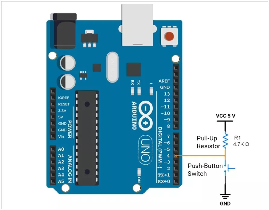
Example: Push-Button Switch Interfacing with Arduino UNO:
Field Issues & Common Mistakes
- Choosing a low-current contact for power switching → overheating.
- Ignoring debounce → erratic readings.
- Using a non-IP-rated switch in an outdoor environment → corrosion failure.
- Poor soldering on THT switches → intermittent contact.
PCB Design Considerations
- Pad size & hole diameter for THT switches — follow datasheet.
- Keep-out zones for actuator clearance.
- Reinforce mounting pads for high-force switches.
- Thermal reliefs for large copper areas.
Failure Modes & Diagnosis
| Failure | Cause | Test |
|---|---|---|
| Contact wear | High current arcing | Measure resistance |
| Dust ingress | No sealing | Visual inspection |
| PCB cracking | Excessive force | Magnification check |
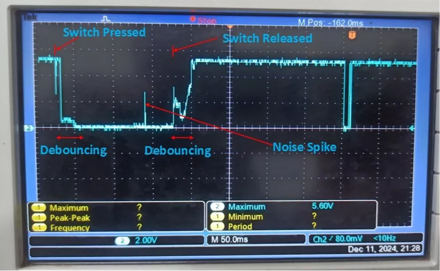
| Bounce issues | Worn spring | Oscilloscope waveform |
Switch Press and Release Oscilloscope Waveform:
ESD/EMI Considerations
- Panel-mounted switches can act as antenna points for ESD.
- Add TVS diodes to MCU lines.
- Use series resistors or ferrite beads for filtering.
- If it's a metal housing, ground it.
Debouncing Methods
- Hardware: RC filter, Schmitt trigger buffer.
- Software: Ignore state changes for a set period (10–50 ms).
- Measurement Tip: Use a scope to capture bounce waveform.
Selection Checklist
- Define the electrical rating needed.
- Pick mounting style (THT/SMD/panel).
- Choose momentary vs maintained.
- Check the IP rating for the environment.
- Confirm mechanical life.
Verify actuator accessibility in the enclosure.
Concept understood? Let's apply and learn for real