Relay Quick Reference Guide
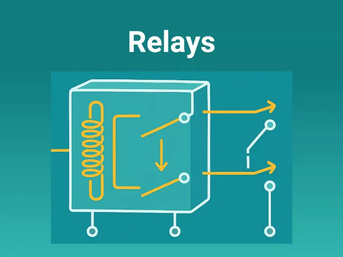
What is a Relay?
A relay is an electrically operated switch that allows a low-power control signal to switch a high-power load.
It acts as a bridge between two circuits:
- Control side — low voltage signals from MCU, sensor, or microcontroller
- Load side — high voltage/high current devices like motors, heaters, or lights
Why Relays Matter in Embedded Systems
- Complete Isolation or Galvanic Isolation: This protects the microcontroller from voltage spikes, electrical noise, and faults coming from the load side
- Control Power Loads: Enables microcontrollers to control motors, lamps, and industrial equipment, etc.
- Versatility: Handles both AC and DC loads interchangeably.
- Compact Control: Avoids bulky manual switches in control panels.
How a Relay Works
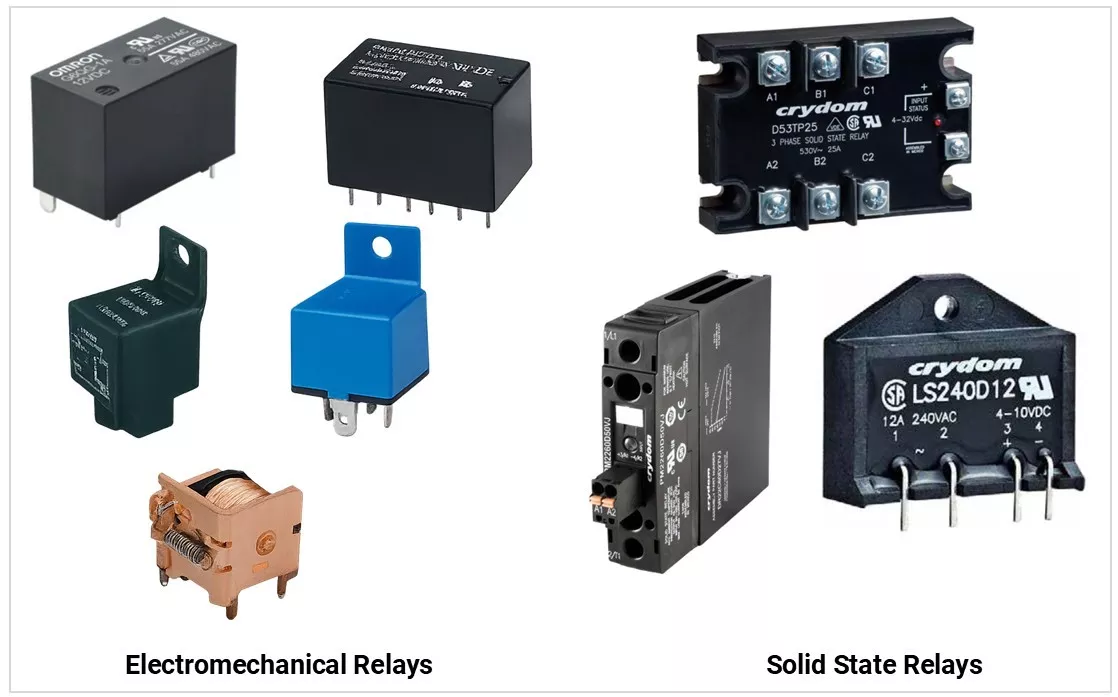
Electromechanical Relay (EMR)
- A coil is energized by a control voltage.
- The coil’s magnetic field pulls an armature, which moves the contacts.
Contacts open or close to control the load.

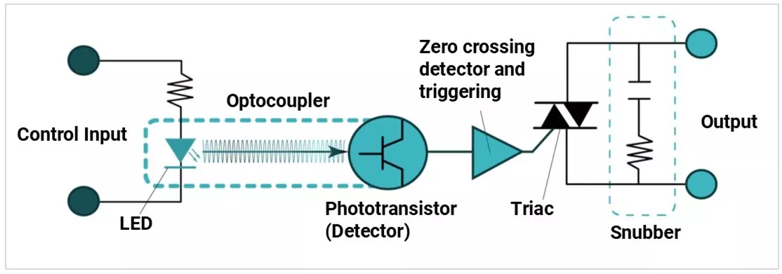
Solid-State Relay (SSR)
- No moving parts — uses optocouplers + semiconductor devices (Triac, MOSFET) for switching.
- Faster, silent, and longer life.
Relay Types
1) Based on the Operation Principle
Type | Image | Description |
|---|---|---|
Electromechanical Relay (EMR) | 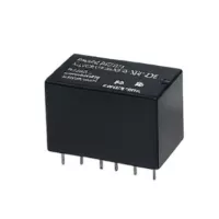 | Uses a magnetic coil to physically move an armature and close/open mechanical contacts. It provides physical "click" feedback and total electrical isolation, but is prone to contact wear and "bounce." |
Solid-State Relay (SSR) | 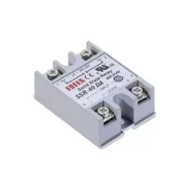 | Uses semiconductor devices (like TRIACs or MOSFETs) to switch the load. Because there are no moving parts, they offer silent operation, extremely long lifespans, and no contact bounce. |
2) Based on Load Type
Type | Image | Description |
|---|---|---|
AC Relays | 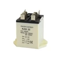 | Optimized for switching Alternating Current (mains power). Designed to handle the rapid voltage reversals of AC, making them ideal for HVAC, lighting, and industrial motors. |
DC Relays | 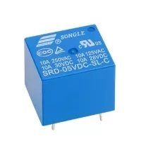 | Built for Direct Current loads like those in automotive systems or battery banks. They often use specialized contact materials because DC arcs are more persistent and harder to extinguish than AC arcs. |
3) Based on Contacts
| Type | Image | Description |
|---|---|---|
SPST (Single Pole Single Throw) | 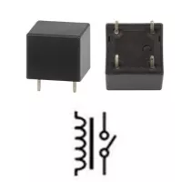 | The simplest form. It has one moving contact (Pole) and one fixed contact (Throw). It acts as a basic ON/OFF switch for a single circuit. |
SPDT (Single Pole Double Throw) | 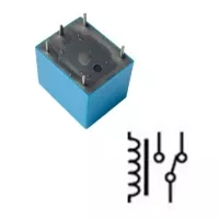 | One pole that can switch between two different contacts. This allows you to select between two different paths or toggle a state (e.g., switching between a "Green" and "Red" indicator light). |
DPDT (Double Pole Double Throw) | 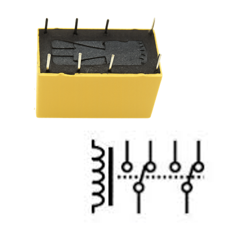 | Essentially two SPDT switches operated by the same coil. It can control two separate, isolated circuits simultaneously, such as reversing the polarity of a DC motor. |
DPST (Double Pole Single Throw) | 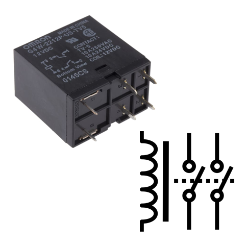 | This relay controls two separate circuits simultaneously using a single input signal. It acts as two independent switches (poles) that either both open or both close at the same time, commonly used to switch high-voltage or high-current |
4) Based on Application
| Type | Image | Description |
| Power Relay | 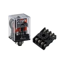 | High-capacity relay for switching heavy AC/DC loads in HVAC and large appliances. |
| Signal Relay | 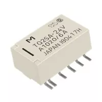 | Low-profile, sensitive relay designed for switching low-level data or audio signals. |
| Automotive Relay | 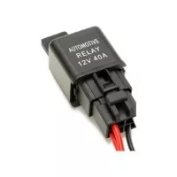 | Ruggedized 12V/24V relay built to withstand the heat and vibration of vehicle engine bays. |
| Reed Relay | 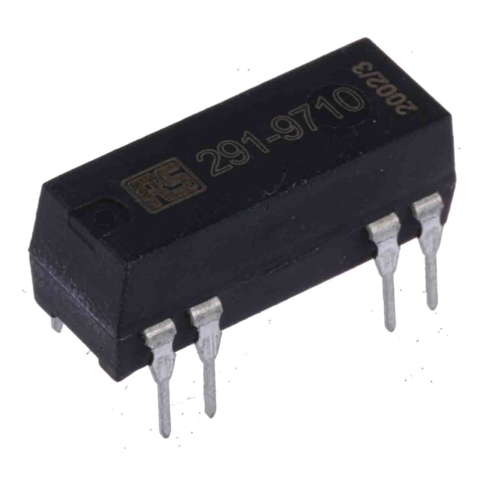 | Fast-acting, magnetically actuated switch sealed in glass for low-power signal integrity. |
| Time-Delay Relay | 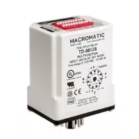 | Includes an internal timer to delay the switching action after a trigger signal is received. |
| Latching Relay | 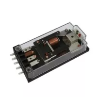 | Bi-stable relay that maintains its last state without constant power to the coil. |
Key Electrical Specifications
- Rated Coil Voltage → Nominal voltage required to energize the relay
- Coil Resistance / Power → Determines current consumption and power loss
- Pull-in Voltage → Minimum voltage at which relay operates (turns ON)
- Drop-out Voltage → Voltage below which relay releases (turns OFF)
- Rated Contact Voltage → Maximum voltage the contacts can switch safely
- Rated Contact Current → Maximum current carrying capacity of contacts
- Switching Capacity (VA/W) → Maximum load power the relay can handle
- Contact Resistance → Resistance across closed contacts (affects efficiency & heating)
- Insulation Resistance → Isolation between coil and contacts
- Dielectric Strength → Maximum voltage the relay can withstand without breakdown
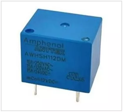
Example General purpose AWHSH112D00G Relay Specifications:
| Specification | Value |
|---|---|
| Rated Coil Voltage | 12 VDC |
| Coil Resistance / Power | 400 Ω / 360 mW |
| Pull-in Voltage | 9 VDC (Max) |
| Drop-out Voltage | 0.6 VDC (Min) |
| Rated Contact Voltage | 240 VAC / 110 VDC |
| Rated Contact Current | 15 A |
| Switching Capacity (VA/W) | 3,600 VA / 1,650 W |
| Contact Resistance | ≤ 100 mΩ (at 1A 6VDC) |
| Insulation Resistance | ≥ 100 MΩ (at 500 VDC) |
| Dielectric Strength | 1,000 VAC (Coil-Contact) / 500 VAC (Open Contacts) |
| Operate Time | ≤ 10 mSec |
| Release Time | ≤ 5 mSec |
Common Real-World Relay Examples
- Single SRD-05VDC-SL-C — low-cost PCB relay.
- Omron G5V-1 — miniature signal relay.
- Omron G3MB-202P — SSR for AC loads.
- Panasonic TQ2 — telecom-grade DPDT relay.
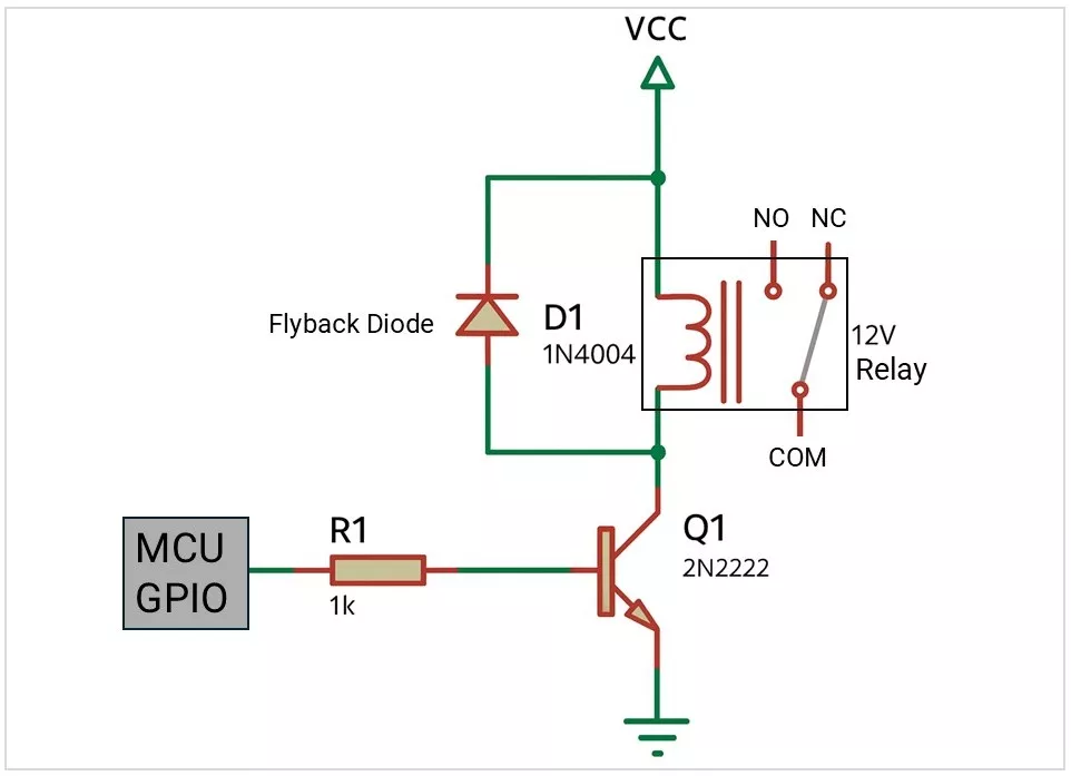
Relay Drive Circuit from MCU
- MCU GPIO →Transistor/MOSFET driver → Relay coil.
- Always add a flyback diode for EMRs.
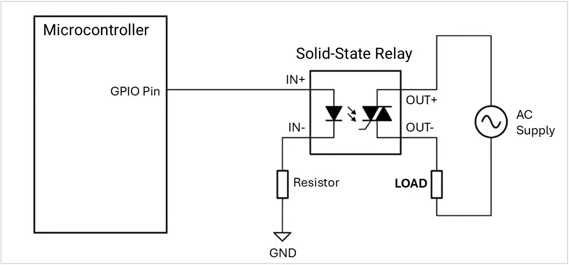
- For SSR, no diode is needed, but an input LED current-limiting resistor is required.
Interfacing an Electromechanical Relay with a MCU using Transistor Driver:
Interfacing a solid-state relay with an MCU:
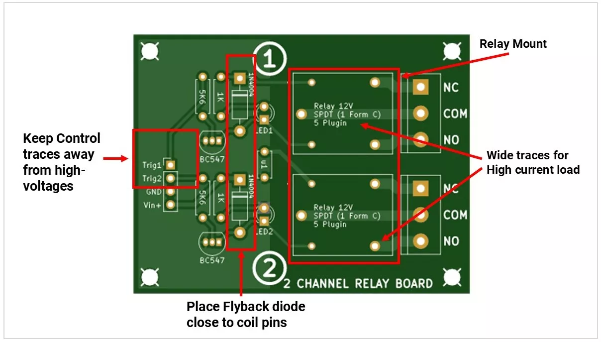
PCB Design & Layout Notes
- Keep high-voltage traces separate from low-voltage control.
- Use wide traces for high current loads.
- Maintain creepage and clearance distances as per safety standards.
- Place the flyback diode close to the relay coil pins.
Protection & Reliability
- Flyback diode – absorbs the coil’s back EMF.
- Snubber network – RC combination across contacts to reduce arcing.
- MOV/TVS – for surge protection on AC loads.
- Contact material – choose gold for small signals, silver alloy for high power.
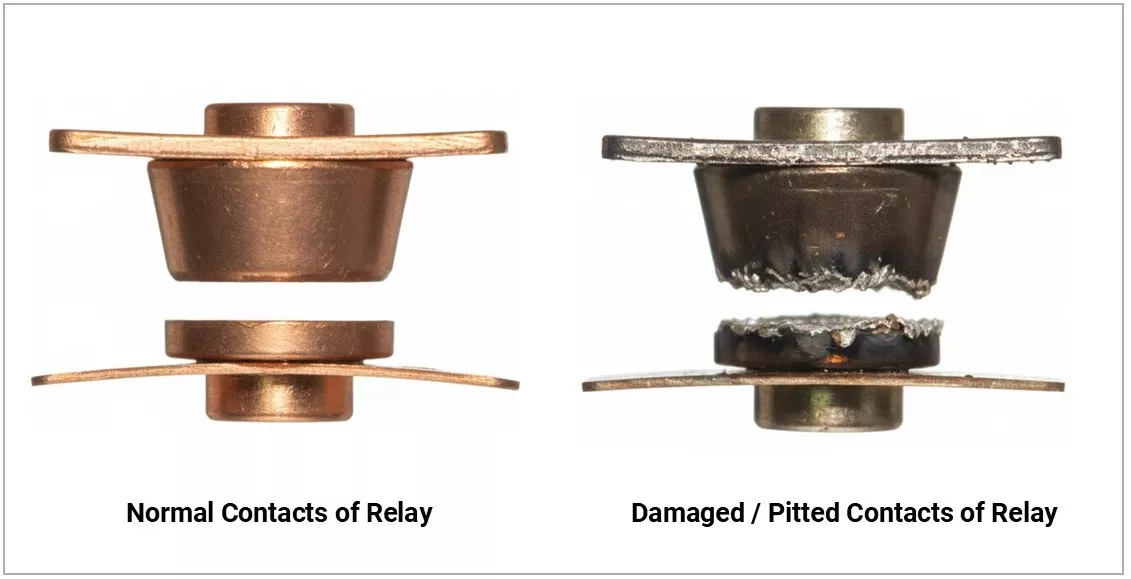
Failure Modes
- Welded contacts – from overcurrent.
- Pitted contacts – from arcing.
- Coil burnout – from overvoltage.
- Stuck armature – mechanical wear.
- SSR leakage – inherent in semiconductor switches.
Testing a Relay
- Measure coil resistance with a multimeter.
- Apply rated coil voltage — listen for a click.
- Measure continuity on NO/NC pins.
- For SSR — test with load or diode-mode check.
Note: Some SSRs may show small leakage current in the OFF state, which is normal and not a fault.
Real-World Applications
- Home appliances (washing machine, AC compressor).
- Industrial automation (PLC control).
- Automotive (headlights, fuel pumps).
- IoT/smart home (mains control from Wi-Fi modules).
Selection Checklist
- Load current & voltage rating.
- Coil voltage (5V, 12V, 24V).
- Drive method (MCU direct, transistor).
- Contact configuration (SPDT, DPDT).
- Isolation requirements.
- Size & mounting style.
- Protection components needed.
Concept understood? Let's apply and learn for real